Read the statement by Michael Teeuw here.
Wife's Valentine's day present - a 37 inch Magic Mirror
-
So, a few months ago, I decided I needed a hobby, so I bought my first Raspberry Pi 3 and learned how to run Amazon’s Alexa service on it. Then, I saw smart mirrors.
I don’t know much about electronics and I hadn’t done any woodworking since high school (30 years?), so my first smart mirror was a test run for my 6 year old - I used an 8 inch display and an 11 x 15 inch mirror. The frame was rough, but it worked.Then, I used a 24 inch TV for my next mirror for my 8 year old. (Both mirrors from Tapplastics.com/product/plastics/cut_to_size_plastic/two_way_mirrored_acrylic/558)
Then, my wife decided she wanted a big one. I found a guy selling a used 37 inch Sharp TV.
I stripped it down to be as thin and light as possible, then promptly shorted out the power control board when I removed too much of the chassis. There was a brief one week delay while I ordered a new board off of Ebay. I figured out how to prevent the shorting out and I was up and running.
I bought a 1/4 inch thick acrylic mirror from Twowaymirrors.com. For my previous 2 mirrors, I had used 1/8 inch acrylic and the reflections were a bit off. Not sure if it’s the thickness, or just better quality, but this mirror is much better.My woodworking skills also got a better the last few months. Hopefully, the frame will hold. This smart mirror is a big sucker. The soundbar on the side and the webcam on top are being used for Alexa still.
I used this software (https://github.com/alexa/alexa-avs-sample-app). It crashes a bit mire now that the Magic Mirror software is running, too. It looks like some folks are working on better Alexa versions that work with MM. Haven’t tried them, yetThanks for taking a look and thanks for the inspiration


-
Nice! Is that the default weather module? How did you manage to make it look like that? If not the default, which weather module is it?
-
@Mate3
Thanks! The weather module is MMM-Wunderground.
It has more detail and has an option to have color icons, which look nice. -
“I stripped it down to be as thin and light as possible, then promptly shorted out the power control board when I removed too much of the chassis.”
I am a little bit nervous stripping recently bought used 42 inch tv down because of this.
What can I do to avoid this kind of mistake? How much is “too much” ?
Thanks, buddy. -
Good question. I had no idea what I was doing. I had made 2 smaller Magic Mirrors before I did this, but the 37 inch-er was much more complicated. In the end, I took off a lot of metal around the periphery that made the screen very hard to handle. The thin LCD itself at that size is much harder to manage. In retrospect, leaving some of that would have been a good idea. Without it, the LCD is just connected to everything else by a couple ribbon cables.
A lot of the metal inside surrounding the circuit boards seemed to be there to isolate the various parts from each other to reduce electromagnetic interference. I was able to remove most of it with no noticeable effect(as far as interference).
However, some of the metal acted as a scaffold for the circuit boards. The ground screws on the circuit board were screwed into some of this metal scaffolding which held the circuit board off the metal back of the TV itself while still grounding it.If you look at the middle picture above, it looks like the video board and power control board (the orange one) are just sitting against the metal. Well, they were initially, but the power control board kept blowing fuses. It took me a while to figure out that some of the circuitry was probably shorting by touching that grounded metal.
In the end, I used these to keep the circuit boards off the metal. But, now the grounding screws weren’t touching anything. To ground it, I cut short lengths of copper wire and connected them to the grounding spots on the circuit board and to the metal backing. (You can see one one the bottom left of the orange circuit board. Just to the right and below the power cord is one of those grounding wired
I know just enough about electricity and circuits to be dangerous. What I cobbled together seemed to work (mirror’s been on 24/7 for 6 weeks), but be careful.
Hope that helps
-
@psm9 Thank you very much for quick and elaborate response.
From what I understand, the first thing to do when stripping down the tv is to
-
Recognize which one the grounding metal.
-
Figure out the grounding spot on the circuit boards.
-
Build standoffs to separate the boards from grounding metal.
-
Connect the grounding spots to the grounding metal.
Is that it? Is there any steps that I missed? You ground all three of the circuit boards, do you?
-
-
At least in my TV, the metal backing seemed to be the ground. All of the circuit boards were screwed into metal scaffolding which in turn was screwed to the metal backing.
The ground connections on the circuit boards were obvious. It’s basically where the screws connect the circuit board to the metal scaffolding. Here’s a close up of the top left corner of that orange circuit board:
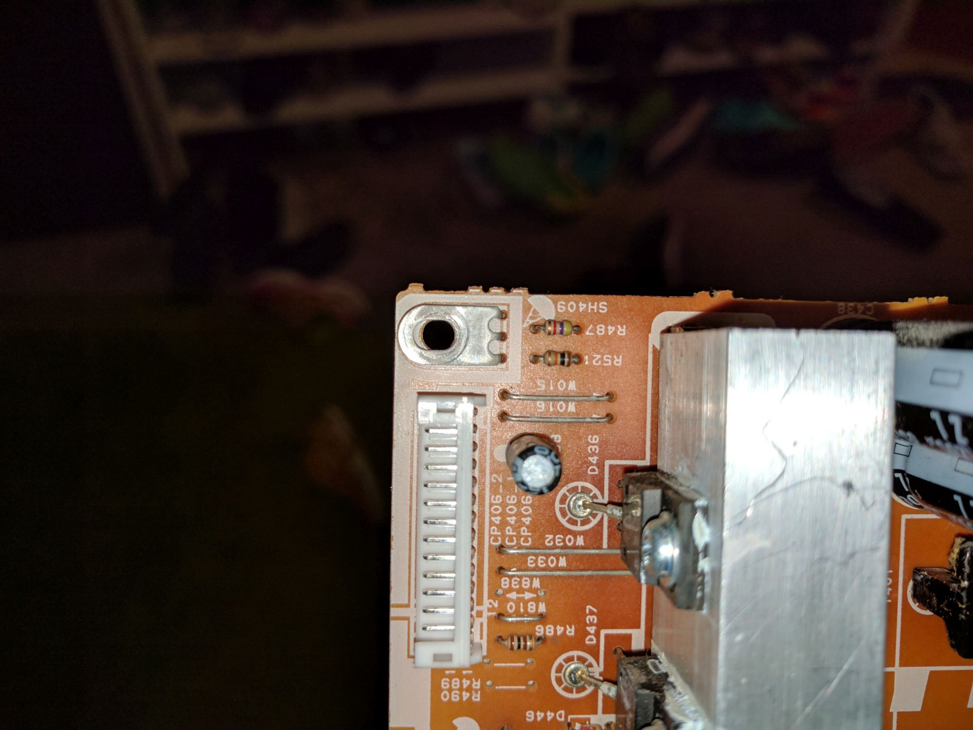
When the screw is in place, it makes contact with that bear-claw looking piece of metal. My understanding is that the various diodes, capacitors, and whatnots ground themselves through that. So, when I used those little plastic standoffs and the screws couldn’t reach, I used the wire to make the connections. If you can find long thin screws, they may work, too. I didn’t ground every one of the screw connections, just as many as I could. Seems to be enough.
The standoffs I bought were easy and built for this purpose. They have adhesive on the bottom, so they stick to the metal backing. Make sure whatever you use is non conductive.
I had to use wire to ground the orange power control board and the large green boards on the right (2 boards, but they’re connected).
The little board at the bottom is exactly as it was when I opened it up. If you zoom, you’ll see that the grounding screws in each corner connect to a little hill on the metal backing. That way it grounds, but keeps the circuits from shorting on the metal.
The board on the left controls the light panel. That one is also left as it was also.
Basically, if you remove enough of the metal scaffolding, you’ll need to make sure you: 1) keep the underside of the boards from touching metal, and 2) ground the boards somehow
Again, this was MUCH easier for 24 inch TVs. Also, - take pictures as you take it apart, so you can reference them later
Good luck!
Hello! It looks like you're interested in this conversation, but you don't have an account yet.
Getting fed up of having to scroll through the same posts each visit? When you register for an account, you'll always come back to exactly where you were before, and choose to be notified of new replies (either via email, or push notification). You'll also be able to save bookmarks and upvote posts to show your appreciation to other community members.
With your input, this post could be even better 💗
Register Login