Read the statement by Michael Teeuw here.
Pin placements -
-
Hello everyone,
I built my MM a couple of years ago and sadly have pulled out some pins from the Rasperberry Pi… I am now completly lost as to how to place them again…
Could someone help me figuring it out again?
The Yellow and Red one are for the Monitor itself - the Black one is for the motion sensor which, according to my config file, should be connected to the Pin 17. However the First pin row had a pin-top thing (the small black things you can slide over them).

-
@Kastore http://pinout.xyz will help you with this now, and in the future.
If the IR sensor is communicating via “17” - it’s likely referring to physical pin 11, actually.
I would highly recommend a more permanent solution… For example, https://www.amazon.com/Status-Terminal-Block-Breakout-Raspberry/dp/B08RDYDG6X/
This is a breakout board for the pi - labels all the IO ports, gives plenty of power, allows you to secure your wires so they won’t just pull out, and as a bonus, allows you to see what your pi is doing on the GPIOs. (pretty blinkin’ lights are always good)
-
@BKeyport
Hey Keyport - thanks for the reply.I was just reeeeally confused since i had a connector on the first pins and that didnt make any sense.
I will def. get one of these boards for my new Mirror as that just makes it so much easier to wire it up and it looks clean!
-
@Kastore It depends on the device but the color of the wires is not random. Typically red = + but could either be 3.3V or 5V. Black will be - or grd. I can’t ever remember all of the pins but if you do an image search on GPIO Pinout you will get a ton of pictures of how all the pins are laid out.
Yellow can be a bit more arbitrary but if you don’t have the device literature you can do a search on the devices name and/or number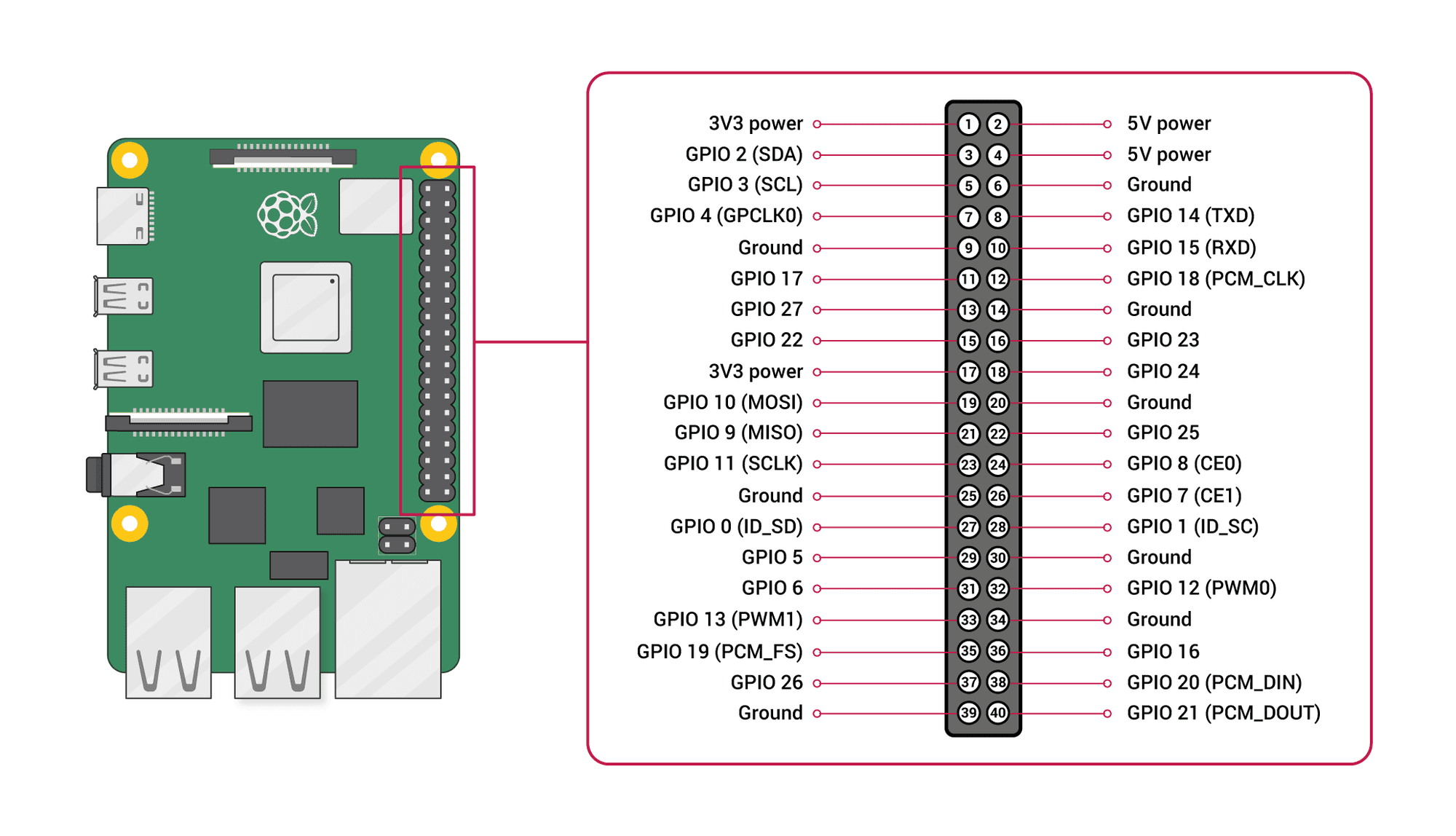
Hello! It looks like you're interested in this conversation, but you don't have an account yet.
Getting fed up of having to scroll through the same posts each visit? When you register for an account, you'll always come back to exactly where you were before, and choose to be notified of new replies (either via email, or push notification). You'll also be able to save bookmarks and upvote posts to show your appreciation to other community members.
With your input, this post could be even better 💗
Register Login