Read the statement by Michael Teeuw here.
Double power supply, different output, for RPI and screen controller
-
@emlowe said in Double power supply, different output, for RPI and screen controller:
the controller itself may have a 5v output already on it that you can use.
I’ve actually used this method on one of my Mirrors before – the driver board for my 27" monitor actually runs the controls on 5VDC and has a 5A polyfuse – I embedded the PI completely inside the back of the monitor housing and just tapped into this power supply to power it.
(one of these days I’ll get a chance to post the full build details)
Another method that I’ve used on a separate project is to buy a cigarette lighter USB charger and use that to convert the 12VDC to the 5VDC for the Pi – something similar to one of these.
-
Hey
Thank you so much for your replies! I didn’t think of converters or even that the controller board might do the stuff! I am new to electronics and I guess I am too afraid to blow up stuff, so if I can avoid building things myself, that’s great. Although, where is the fun in that ;)
I am still waiting for my controller to be delivered, here it is: https://www.ebay.fr/itm/NT68676-HDMI-DVI-VGA-LCD-Screen-Controller-Board-Kit-for-15-4-B154EW04-V-B-VB/122620926961?ssPageName=STRK%3AMEBIDX%3AIT&_trksid=p2057872.m2749.l2649
And the specs sheet I found: http://www.vslcd.com/Specification/M.NT68676.2A.pdf
Seems like there is a power supply too but it points to nothing on the board. Any thoughts?I am though concerned about the intensity for the Raspberry. How can I make sure I much amps I need to power it, from 2.5 to let’s say 4 amps. For now I am not planning on plugging anything to it yet, except maybe for a PIR or some other motion sensor and audio later. Cherry on the cake would me a microphone for voice command. But see… do this mean I may need to rethink the power supply as I upgrade my mirror?
Thank you for your help!
Clément -
The Pi itself doesn’t drain much power. It is suggested to use a 2.5A power supply to utilize the 4 USB ports. A PIR sensor or a microphone consume close to no power. So I am pretty sure 1A should be enough already. I know in my case the Pi drains 560mA at max, running MM (using WIFI, USB keyboard dongle, temperature sensor and PIR sensor).
I am using a 0,20€ 3A buck converter for my Pi, which is powered by the 12V power supply for my LCD. Runs flawlessly for 3 months now continuously.
-
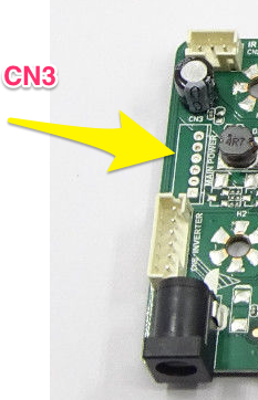
In the spec sheet you posted, see where it says CN3 on page 4 &5. This is an optional connector that may (or may not) be on the board.
Pins 3 & 4 are 5v and 5 & 6 are GND.
Note, however, unless you want to do some simple PCB soldering this isn’t the way to go. What I did was attach some header pins to the board, cut one end off a USB cable and attached it to the pins, then plugged it in the normal way into the RPi.
-
I usually mount a power strip along the inside edge of the frame and run the Pi from there. This one pushes 2.4A on each of 4 USB ports. I use one for the Pi and one for an LED strip light around the frame. Here’s the one I normally order: http://a.co/evJGa7V
@shbatm - I put one of those USB plugs on my motorcycle and it was insanely easy. They’re compact and push good current. That sounds like a good idea.
-
Thank you guys!
The 5V off the board sounds like a great idea, at least if the model I get has that (the pic on ebay seems to show it).
But if I power the controller board with 12V 3A like recommended and pull 2 cables for a micro USB plug the 5V output (pins 3 and 5 (gnd) let’s say) for the RPI, how do I know how much amp the RPI could (or will) “suck” from there? Because obviously, the screen will drain some power, how can I know what would be left and won’t it be too much or too little?
This is probably basic electronics, I will search on that now but if you have a simple answer for me, I’d take it!
Thank you a lot!
Clément -
I used a 12v 5a power supply with the same board - you don’t have to stick with 3a, that’s a minimum recommendation for the controller. So getting a 5a power supply should cover easily the controller and the rpi.
-Earle
-
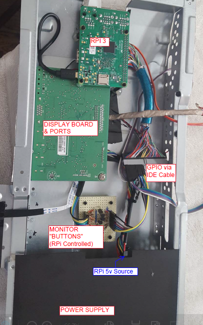
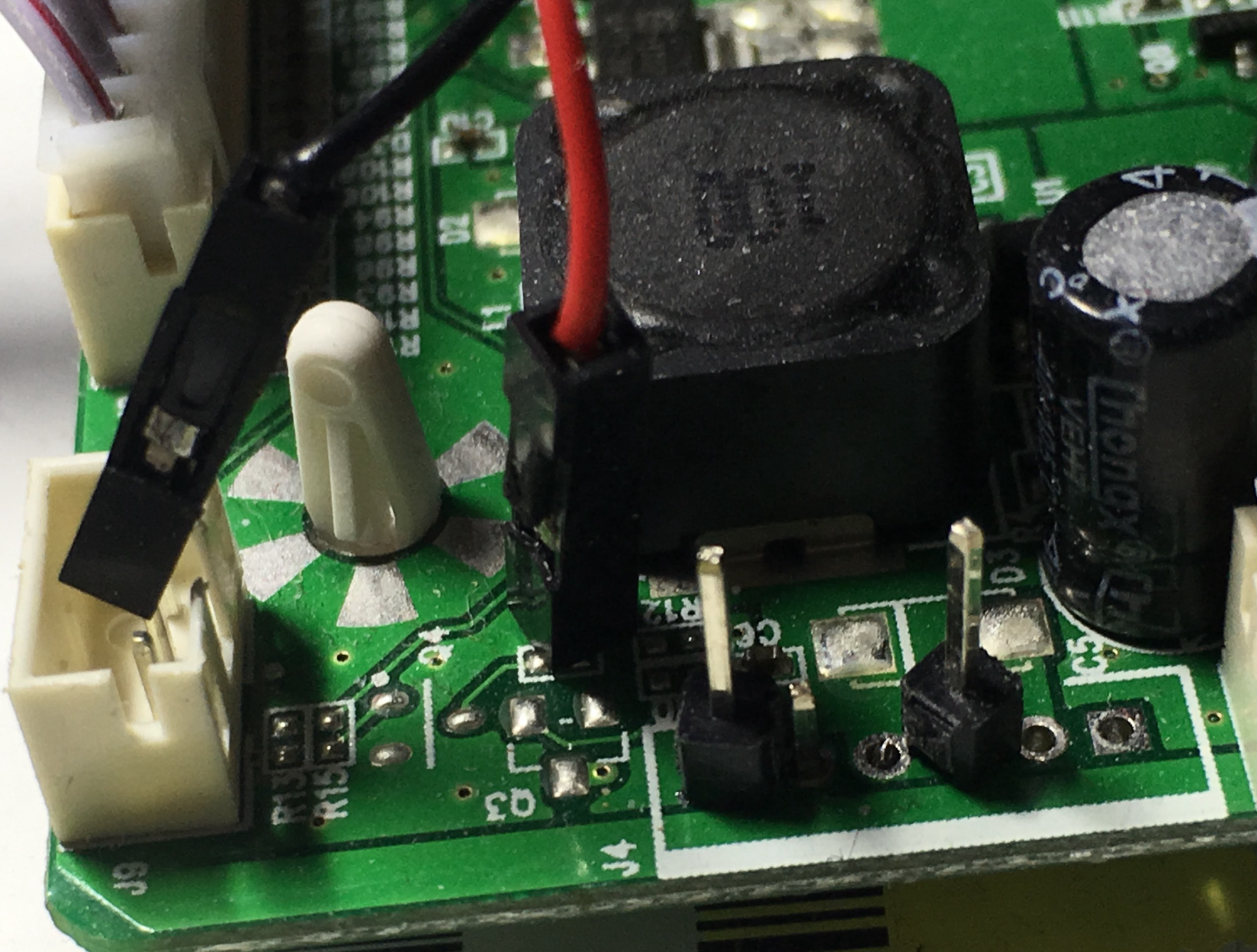
I’m terrible with the soldering iron but here is what I did
-
Ok awesome thanks! Lucky for you we don’t see the solder on the picture ;) but I get what you did! Thanks a lot for the advise.
Will keep the post updated when I get the stuff
Clément
-
Hi,
I received the monitor controller board way early than expected and got a power supply from Amazon (12V 5A to get enough juice for the board and the RPI as advised):
https://www.amazon.fr/gp/product/B01LT77HW6/ref=ox_sc_act_title_1?smid=A30SNSYXWKC8W6&psc=1
I am very happy to announce that my old laptop’s screen works!

And the board has indeed a 5V output which I tested and seems to work fine!
Next step: get some header pins and cable to power up the RPI from the controller board!
Thank you guys again for your advise.
Have a good weekend