Read the statement by Michael Teeuw here.
Double power supply, different output, for RPI and screen controller
-
Hi,
I am gathering parts to build my very first MagicMirror and I am looking for a way to power up the mirror with only one plug.
I have a Raspberry Pi 3 that requires (if I am not wrong) 5V 2.1A. And I just ordered that screen controller for my old laptop’s monitor which I am gonna use: https://www.ebay.fr/itm/122620926961. This requires 12V 3A power supply.
Do you know what I can search for to find a power supply that can provide these 2 outputs?
I found this on Amazon but the 12V output handles a max intensity of 2A and I would need 3: https://www.amazon.com/Universal-CUGLB-Switching-Selectable-Electronics/dp/B074FT2LXDThank you for your help!
Have a good day ;)
Clément -
Find a good 12VDC power supply that fits the needs of your display and then look on eBay or AliExpress for a 5V Buck Converter similar to one of these below – this would allow you to drop the 12V down to 5V for the RPi:
-
The recommended power supply for the 3B is 2.5A
the first buck converter mentioned before is not powerfull enough to power a 3B (it might work when the Pi 3B is not doing anything but under high load you might get the dreaded “insufficient power” error.
The second one provides 3A and should be sufficient… unless when you want to play audio from your raspberry pi…In that case i’d go for a 6A 12V power supply and a 5V isolated step down converter.
They are not cheap… but they provide 3A instead of 2A and if you want to play audio from your raspberry pi, it is better to go for an isolated step down converter… and I had to learn this the hard way… as with a normal 5V buck converter I had a ton of strange noises coming out of the speakers (and it wasn’t a ground loop). Several cheap buck converters and hours later it became clear that I needed an isolated one:
Look for a Mornsun VRB1205LD (there are cheaper ones out there, I just copied the first one):
-
Depending on which controller board you actually end up with (sometimes ebay gives out different ones) - the controller itself may have a 5v output already on it that you can use.
-
More specifically:
(http://www.panelook.com/upload/201511/MNT686762A_12516-Specification_A2_(1)_201511187301.pdf)
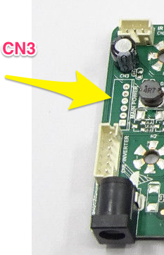
Supplies 5v on the CN3 pins (probably headless on the board, but 5v is there)
This guy says it’s good up to 1.5 amps (https://www.raspberrypi.org/forums/viewtopic.php?t=67312)
I’ve confirmed that this is there and can indeed power the rpi - however, you if you need to power USB devices from the pi, it may not be enough.
-Earle
-
@emlowe said in Double power supply, different output, for RPI and screen controller:
the controller itself may have a 5v output already on it that you can use.
I’ve actually used this method on one of my Mirrors before – the driver board for my 27" monitor actually runs the controls on 5VDC and has a 5A polyfuse – I embedded the PI completely inside the back of the monitor housing and just tapped into this power supply to power it.
(one of these days I’ll get a chance to post the full build details)
Another method that I’ve used on a separate project is to buy a cigarette lighter USB charger and use that to convert the 12VDC to the 5VDC for the Pi – something similar to one of these.
-
Hey
Thank you so much for your replies! I didn’t think of converters or even that the controller board might do the stuff! I am new to electronics and I guess I am too afraid to blow up stuff, so if I can avoid building things myself, that’s great. Although, where is the fun in that ;)
I am still waiting for my controller to be delivered, here it is: https://www.ebay.fr/itm/NT68676-HDMI-DVI-VGA-LCD-Screen-Controller-Board-Kit-for-15-4-B154EW04-V-B-VB/122620926961?ssPageName=STRK%3AMEBIDX%3AIT&_trksid=p2057872.m2749.l2649
And the specs sheet I found: http://www.vslcd.com/Specification/M.NT68676.2A.pdf
Seems like there is a power supply too but it points to nothing on the board. Any thoughts?I am though concerned about the intensity for the Raspberry. How can I make sure I much amps I need to power it, from 2.5 to let’s say 4 amps. For now I am not planning on plugging anything to it yet, except maybe for a PIR or some other motion sensor and audio later. Cherry on the cake would me a microphone for voice command. But see… do this mean I may need to rethink the power supply as I upgrade my mirror?
Thank you for your help!
Clément -
The Pi itself doesn’t drain much power. It is suggested to use a 2.5A power supply to utilize the 4 USB ports. A PIR sensor or a microphone consume close to no power. So I am pretty sure 1A should be enough already. I know in my case the Pi drains 560mA at max, running MM (using WIFI, USB keyboard dongle, temperature sensor and PIR sensor).
I am using a 0,20€ 3A buck converter for my Pi, which is powered by the 12V power supply for my LCD. Runs flawlessly for 3 months now continuously.
-
In the spec sheet you posted, see where it says CN3 on page 4 &5. This is an optional connector that may (or may not) be on the board.
Pins 3 & 4 are 5v and 5 & 6 are GND.
Note, however, unless you want to do some simple PCB soldering this isn’t the way to go. What I did was attach some header pins to the board, cut one end off a USB cable and attached it to the pins, then plugged it in the normal way into the RPi.
-
I usually mount a power strip along the inside edge of the frame and run the Pi from there. This one pushes 2.4A on each of 4 USB ports. I use one for the Pi and one for an LED strip light around the frame. Here’s the one I normally order: http://a.co/evJGa7V
@shbatm - I put one of those USB plugs on my motorcycle and it was insanely easy. They’re compact and push good current. That sounds like a good idea.