This is my Smart mirror, there is many like it, but this one is mine
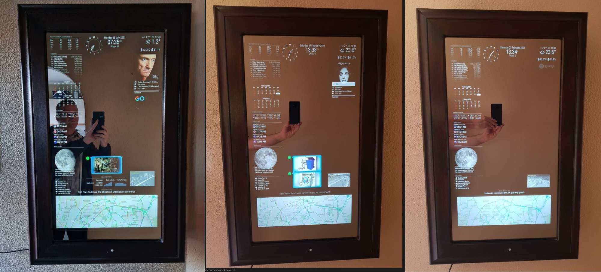
Let’s start with all my modules. The modules listed below is modules that is not in the default installation and were all added after the mirror installation
MMM-NowPlayingOnSpotify
MMM-DHT-Sensors
MMM-Multimonth
MMM-CurrencyExchange
MMM-Worldclock
MMM-Lunartic
MMM-NetworkScanner
MMM-Bingmap
MMM-iFrame
MMM-GoogleAssistant
MMM-TelegramBot
MMM-Alexa
MMM-Detector
MMM-PIR-Sensor
MMM-COVID19-SPARKLINE
Special thanks to all the module creators. Your time and effort and after development support is highly appreciated by us all.
My Glass
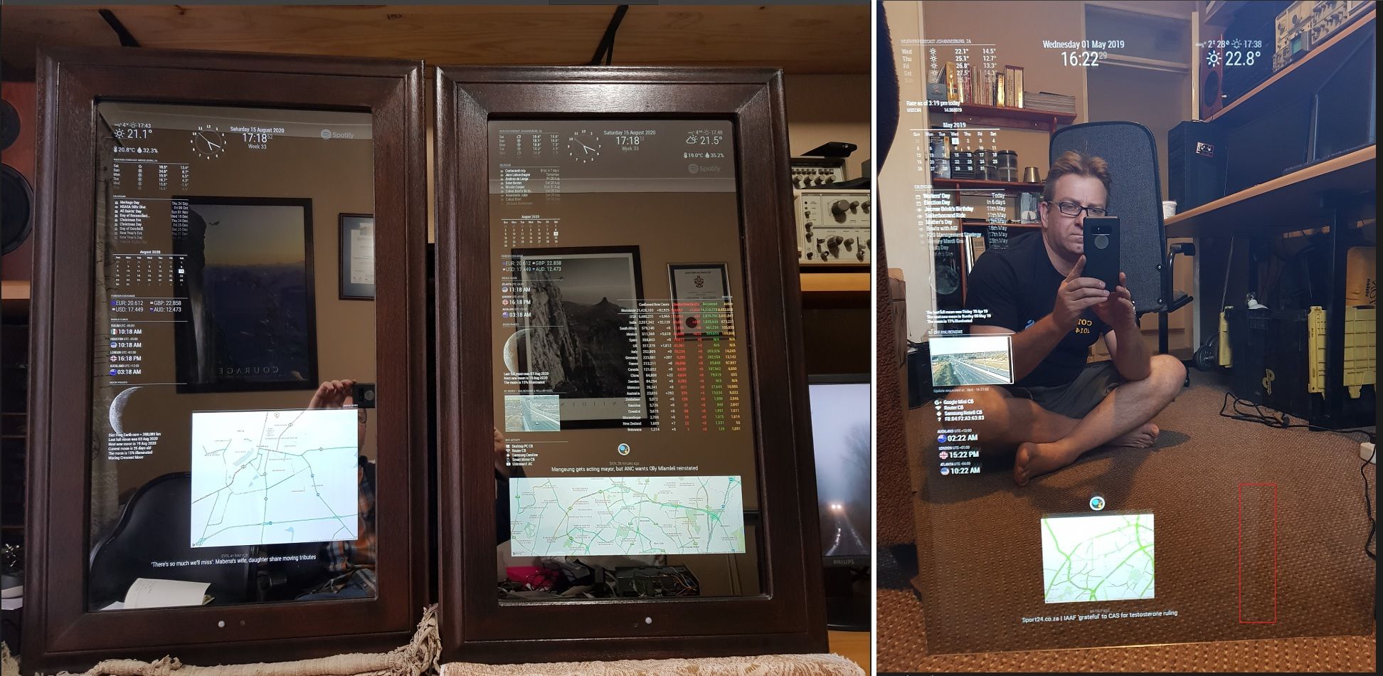
I have decided to work with glass instead of film. The glass that I used is called S10 one-way mirror. There are basically two types of S10 glass that I worked with. The one is a golden look (Left Mirror) and the other is a dark smoked look (Right Mirror). I have literally no favourite. They are very similar once the screens are lit up. The monitor always leaves a light footprint as can be seen on the far-right picture. You will notice the light stripe in the rectangular red box. Take care with regards to this when designing your mirror. For this reason, I won’t advise a small monitor behind a big mirror and/or an off-center screen.
Raspberry
I started the project with a Pi3B+ with a 16GB card. I would highly recommend to rather use a Pi4 4GB and a 32GB Micro SD card which I am currently running. The 16GB become too small after updates and the 3B+ just isn’t powerful enough
GPIO
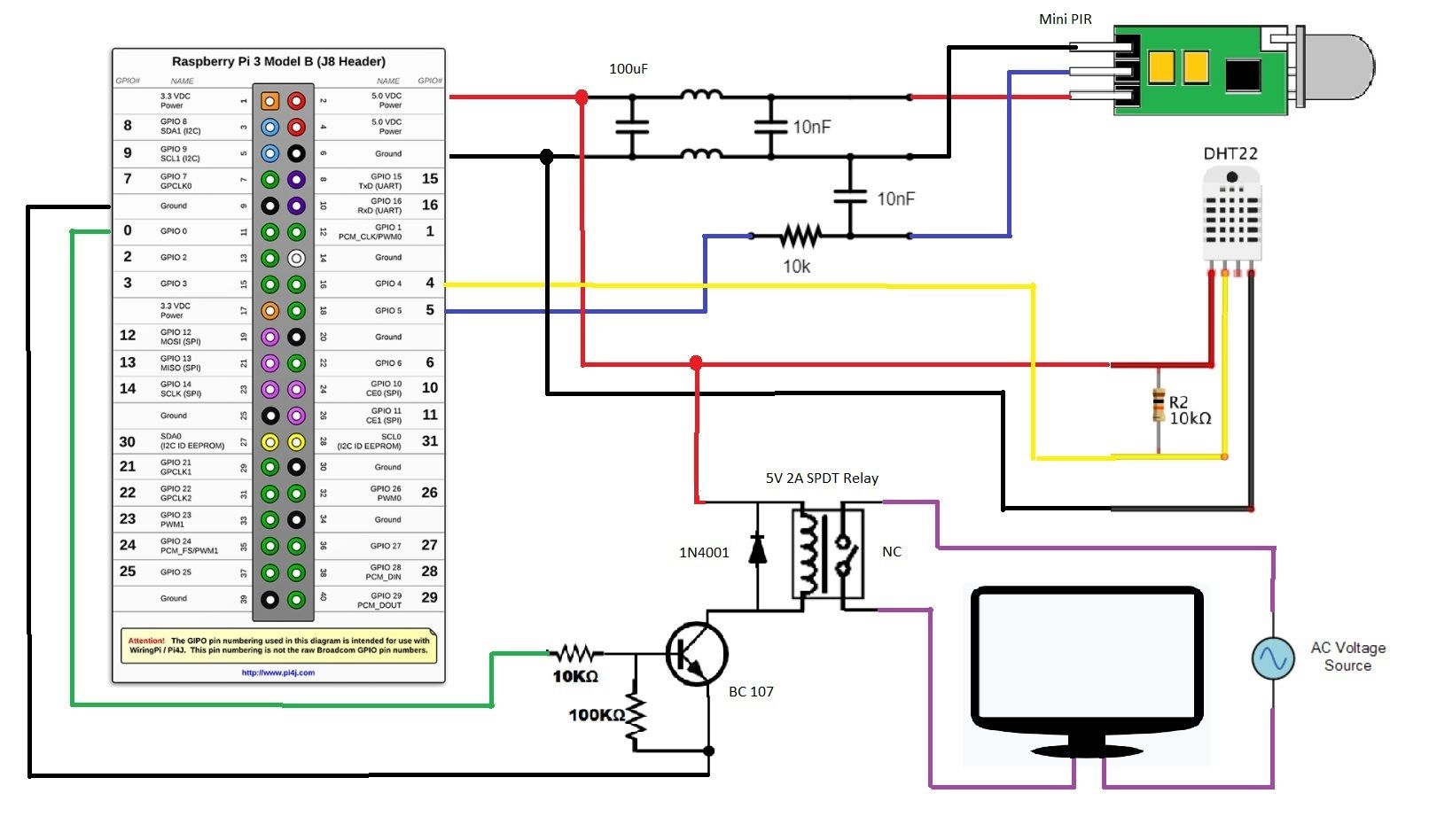
Below is a basic wiring diagram, the way my GPIO is connected to my sensors and switching relay. I decided the best way to approach this is to build an interface board. I had a bit of trouble with false triggers on my PIR sensor. I realised that the sensor was too close to the pi and that the WiFi chip induced EMF into the PIR sensor. I solved this by moving the sensor further away as well as introducing a low pass filter.
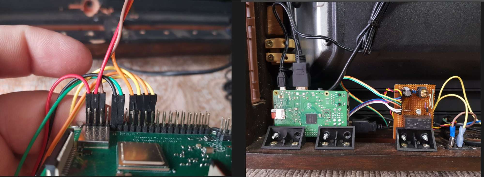
Components
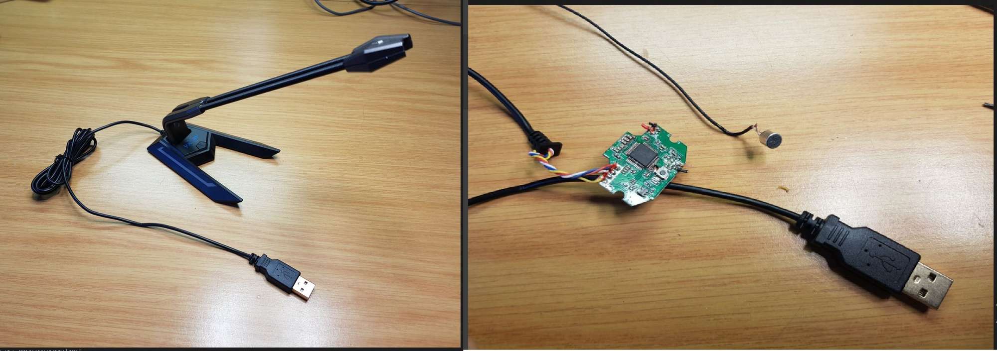
I purchased a USB microphone which I stripped to component level. This makes for easy installation and hiding the mic.
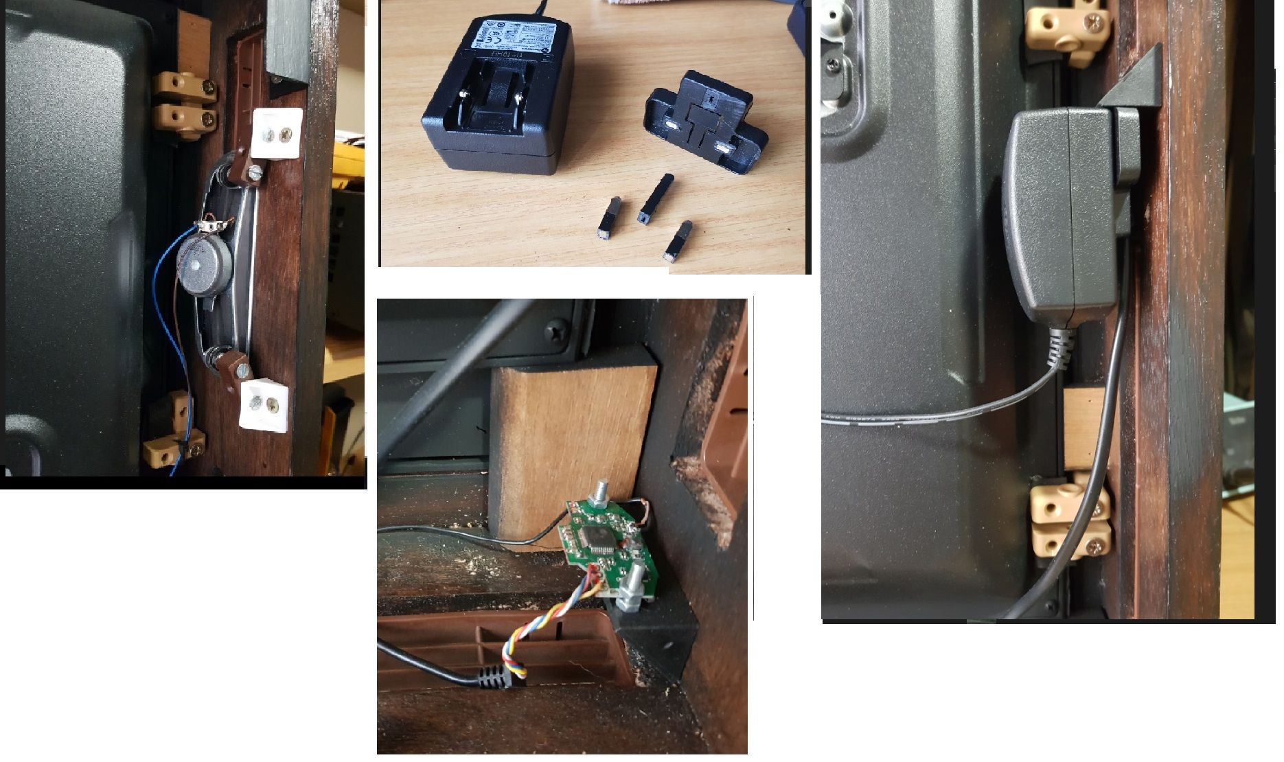
I used the speakers that came with the LED TV. Doing this enables me to use my audio on the HMDI cable with an amp and speakers that’s correctly configured. I also used the RPI PSU and soldered wires to the connector pins that I removed.
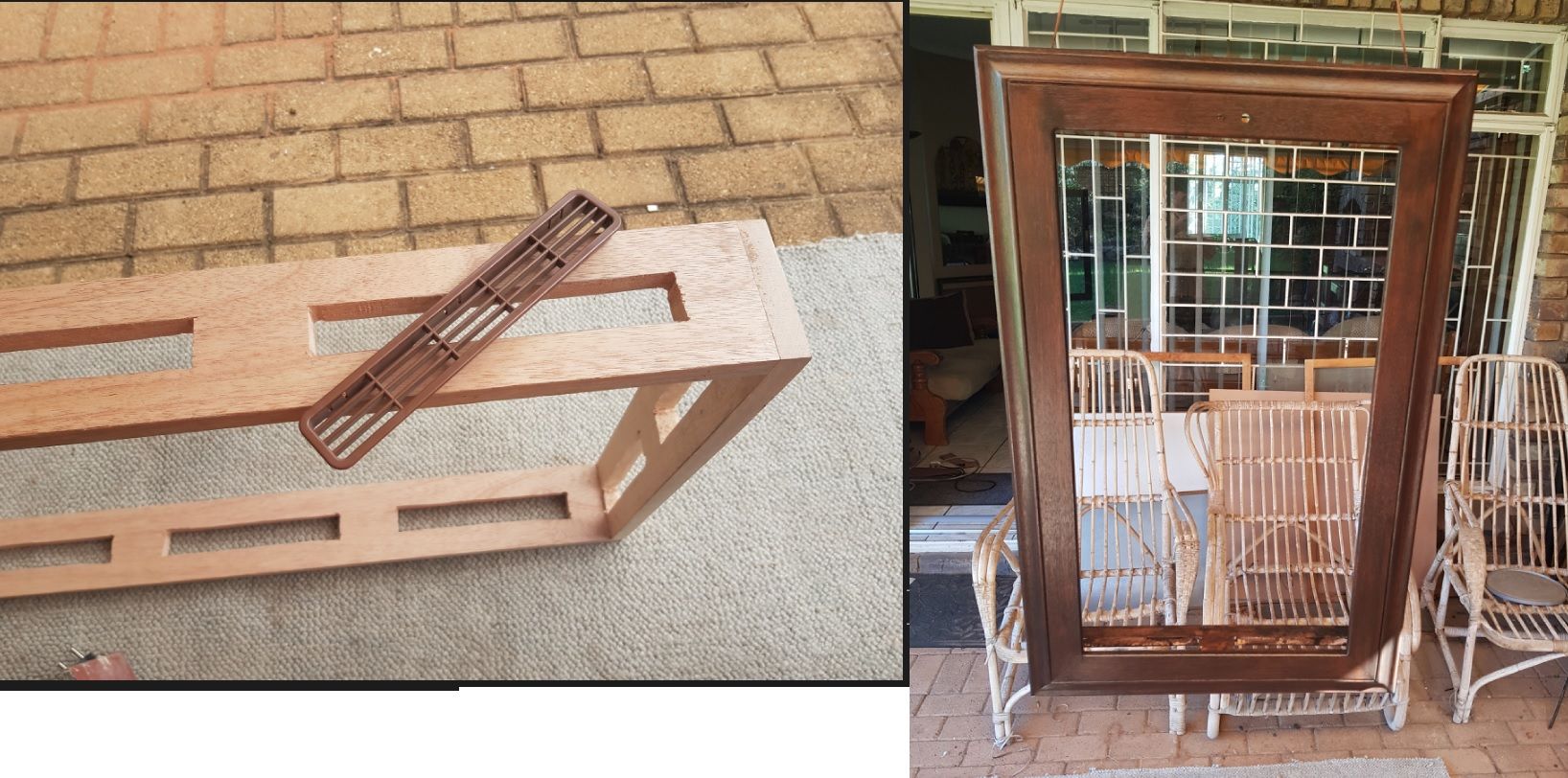
At the bottom of the screen I left myself a bit of space for the component installation. This became really handy not to have a cramped environment for the Pi and the interface board.
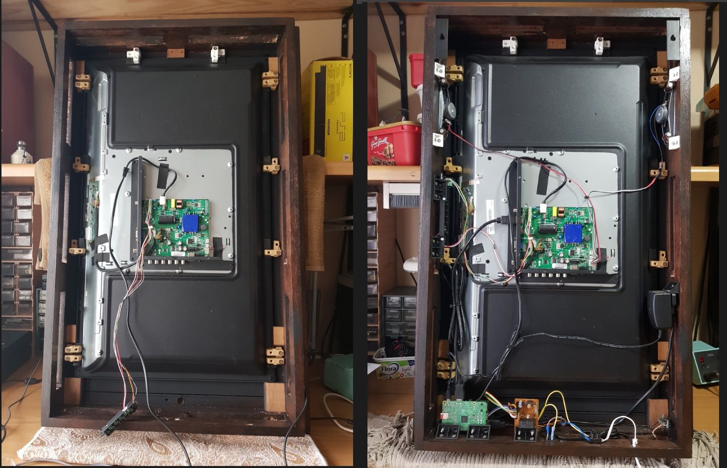
Assembly
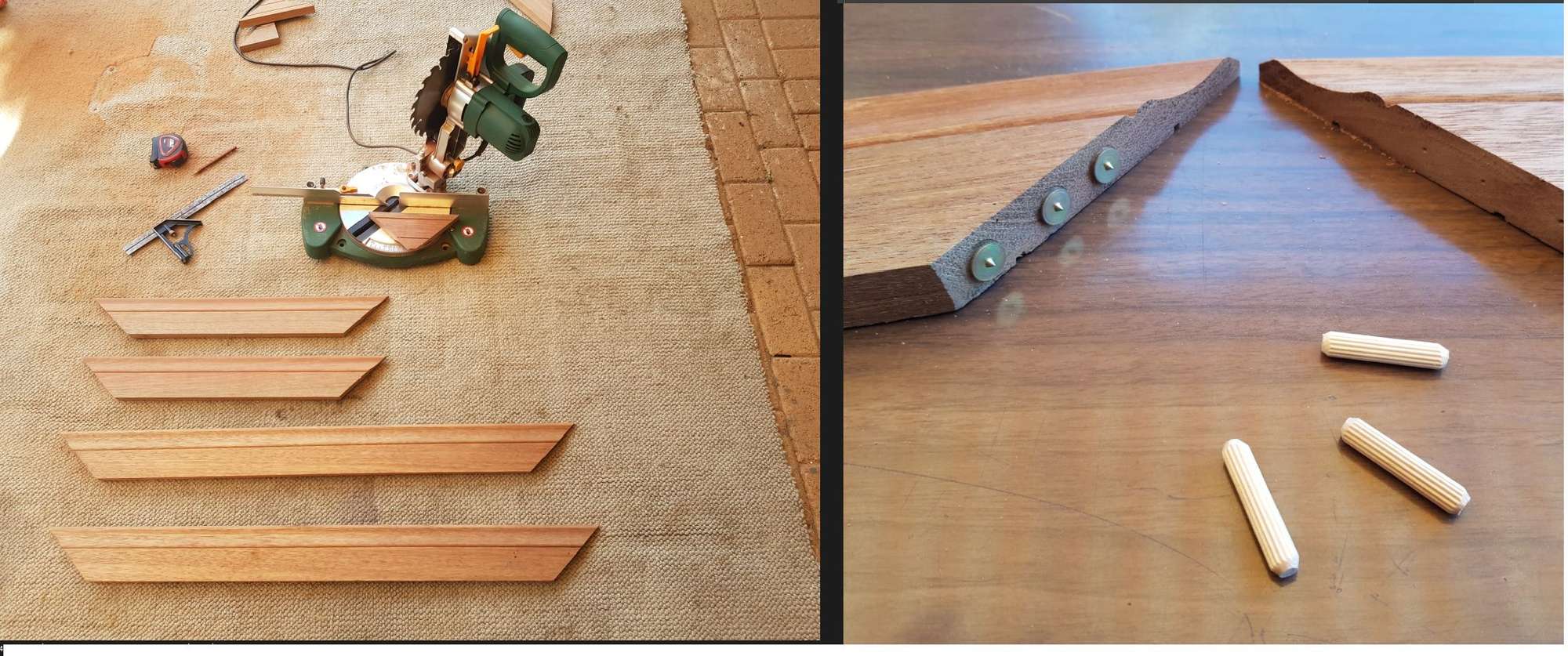
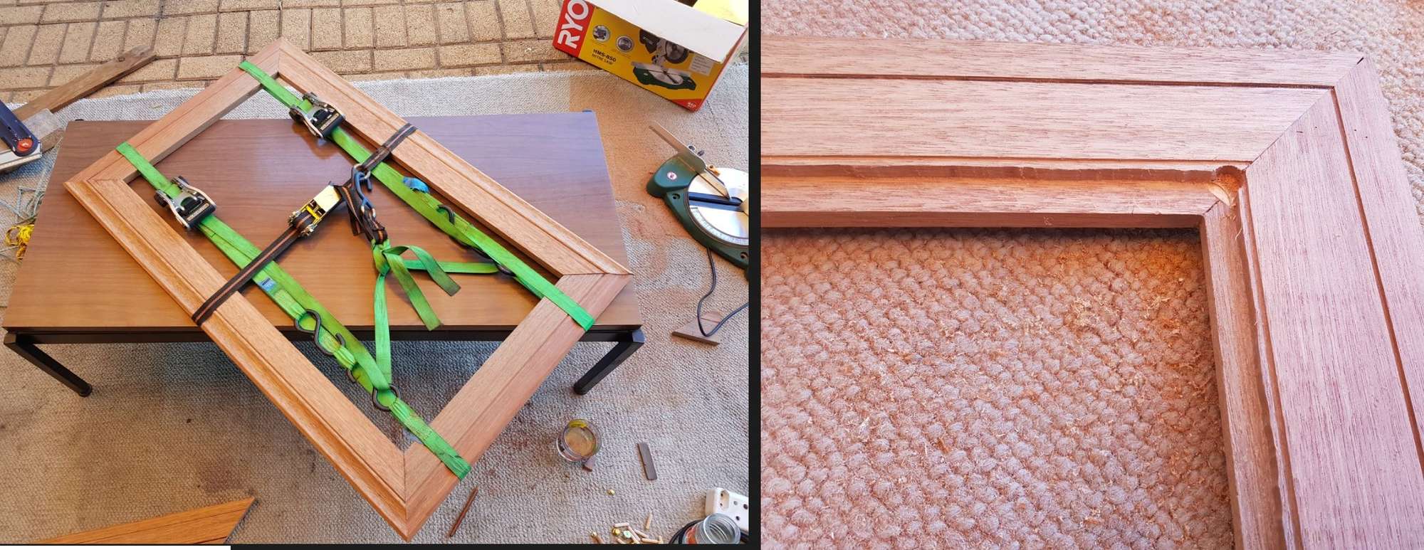
I used skirting for the frame. The nice thing about this is there is an existing machined boarder and no additional rotor work is needed. Just ensure that you have enough inside flesh available to have enough space to router for the glass, brackets and box assembly. I used dowels for the corners as well as the box mount on the frame. Tie downs also work great to pull everything together for the glue to set.
Cost
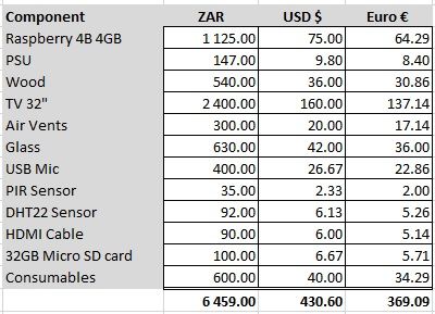
Below is a quick cost calculation on my mirror.
