MagicMirror Forum
    • Recent
    • Tags
    • Unsolved
    • Solved
    • MagicMirror² Repository
    • Documentation
    • 3rd-Party-Modules
    • Donate
    • Discord
    • Register
    • Login
    A New Chapter for MagicMirror: The Community Takes the Lead
    Read the statement by Michael Teeuw here.

    PIR Sensor: false positive detections

    Scheduled Pinned Locked Moved Hardware
    18 Posts 6 Posters 7.9k Views 6 Watching
    Loading More Posts
    • Oldest to Newest
    • Newest to Oldest
    • Most Votes
    Reply
    • Reply as topic
    Log in to reply
    This topic has been deleted. Only users with topic management privileges can see it.
    • MZ-BERM Offline
      MZ-BER
      last edited by MZ-BER

      Hey folks - Ive added a new gadget to my MagicMirror: HC-SR501 PIR sensor. I was able to set it properly up with MMM-NewPIR. But I noticed that I have a lot of false positive detections (every 4-5 min.). Even if my sensitivity is as low as possible.

      Do you have any recommendations to reduce the false positive rate?

      S FoziF 2 Replies Last reply Reply Quote 0
      • S Offline
        Stefan723 @MZ-BER
        last edited by

        Hi @mz-ber ,

        That is strange, do you have any movement at all or none?
        I am using a different module (MMM-PIR-Sensor) and mine is working perfectly.
        For starters I’d eliminate magic mirror and just observe the behaviour on the command line, there are python libraries to monitor the sensor and to check that it is working correctly independently of magic mirror.
        Hope this helps at least a bit,
        Stefan

        thgmirrorT 1 Reply Last reply Reply Quote 0
        • thgmirrorT Offline
          thgmirror @Stefan723
          last edited by

          @stefan723 May be, a so called “Step Down” resp. “Step Up”-resistor is needed. The PI has built-in Step Down/Up functionality.
          The issue may arise due to interferencies from other parts around the sensor and the PI. First follow the idea of @Stefan723 and try to use short cables.
          Use Google to search for “Step Down/Up and Raspberry PI”.

          But I’m a programmer…not an electrician:-)

          1 Reply Last reply Reply Quote 1
          • P Offline
            philmavedzenge
            last edited by

            I had the same issue for some time, it turned out to be the time in between detections was too long. the sensor would detect movement and keep that state until the set time and then checks again. Play around with adjusting one of the orange screws on the sensor until the detection time is very low.

            1 Reply Last reply Reply Quote 0
            • FoziF Offline
              Fozi Project Sponsor @MZ-BER
              last edited by

              @mz-ber said in PIR Sensor: false positive detections:

              HC-SR501 PIR

              I’m with @Stefan723. I had used MMM-NewPIR in the past but switched back to MMM-PIR-Sensor again for reasons. MMM-PIR-Sensor is simple, robust and does the job reliably. May be you have some intereferences, too, which trigger false positives.
              Due to the proximity of the Vout and GND wires to the WLAN module, unwanted interferences may occur which might prevent the PIR sensor to switch from high (motion detected) to low state (no motion detected). The wires work like an antenna in that case. As a result, the display will stay on. A ferrite bead attached to those wires, e.g. taken from an old VGA cable, reduces the interferences and allows for correct state change.

              Hope that helps.

              HowTo: Replace PIR Sensor with a RCWL-0516 Microwave Sensor

              Z 1 Reply Last reply Reply Quote 0
              • Z Offline
                Zoltan @Fozi
                last edited by

                @fozi I also had false triggers. It turned out that my PIR was too close to my Pi and the WiFi chip induced EMF into the PIR. By moving the PIR further away and introducing a low pass filter i solved my issue. Have a look at my circuit and comments

                https://forum.magicmirror.builders/topic/15458/smartmirror-dashboard

                FoziF MZ-BERM 2 Replies Last reply Reply Quote 0
                • FoziF Offline
                  Fozi Project Sponsor @Zoltan
                  last edited by

                  @zoltan Really nice build!Congrats!
                  Yeah, a low-pass filter can solve the interferences from the WiFi module, too, of course. But due to my lazyness and impatience I sacrificed an old VGA cable and re-used the ferrite bead:beaming_face_with_smiling_eyes:

                  HowTo: Replace PIR Sensor with a RCWL-0516 Microwave Sensor

                  1 Reply Last reply Reply Quote 0
                  • MZ-BERM Offline
                    MZ-BER
                    last edited by

                    Hey folks - thanks for your answers. I decided to goahed with a RCWL-0516. But have the same issues. I’m testing the sensitivity with a python script. I also covered it in alu foil - no change. Now I ordered a ferrite beat and will add to the cables (around all of the them or only GND, 5v or Output?)

                    I’m also thinking about adding a low pass filter, but I have no experience with that. Where do I have to add that? GND & Output?

                    FoziF 1 Reply Last reply Reply Quote 0
                    • FoziF Offline
                      Fozi Project Sponsor @MZ-BER
                      last edited by

                      @mz-ber Just put all wires through the bead.
                      With the RCWL-0516 you should note that they can be very sensitive (up to 7m on free sight) and detect motion even through walls. First I went the alu foil route, too, but then modded my RCWL-0516 with a trimmer. Now the mirror is triggered when I approach the mirror less than 1m. Check the link in my signature for details, if you like.

                      HowTo: Replace PIR Sensor with a RCWL-0516 Microwave Sensor

                      MZ-BERM 1 Reply Last reply Reply Quote 0
                      • MZ-BERM Offline
                        MZ-BER @Fozi
                        last edited by

                        @fozi Yes! I followed your instructions in detail - that was very helpful. And yes, I noticed how sensitive it is. In your tutorial you removed the the tiny SMD resistor soldered and replaced that. What if I just remove it and not replace it. Is the range than completely gone and doesent work anymore?

                        FoziF 1 Reply Last reply Reply Quote 0
                        • MZ-BERM Offline
                          MZ-BER @Zoltan
                          last edited by MZ-BER

                          Hi @zoltan - I was reviewing your tutorial. Really good documented. I have a question about the wiring drawing you shared. I’m new to it and dont understand everything. But I’m a fast learner :-)

                          In your drawing you added a couple of symbols. I guess these are resistors and filters, right?

                          Numbers 1, 2 and 3 look similar, only with a diffrent capacity. Is that a Capacitor?
                          What are 4 and 5? Is that a conductor? What capacity is here needed?
                          And number 6, not sure. Is that a RND or a resistor?

                          592b9840-5b90-4d92-9bd3-b79a1f1176ad-image.png

                          Z 2 Replies Last reply Reply Quote 0
                          • FoziF Offline
                            Fozi Project Sponsor @MZ-BER
                            last edited by

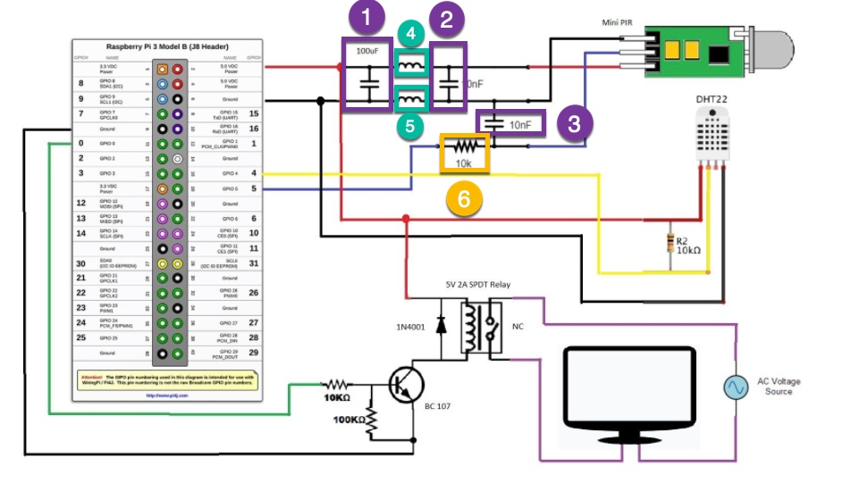
                            @mz-ber If you remove the resistor completely without any replacement the sensor won’t work any more.

                            HowTo: Replace PIR Sensor with a RCWL-0516 Microwave Sensor

                            1 Reply Last reply Reply Quote 0
                            • thgmirrorT Offline
                              thgmirror
                              last edited by thgmirror

                              Didn’t I said, I’m not an electrician?
                              It is not a step-down/up … it is called Pull-Up, resp Pull-Down.
                              Please see here for detailed (german) explanation: https://www.elektronik-kompendium.de/sites/raspberry-pi/2006051.htm

                              MZ-BERM FoziF 2 Replies Last reply Reply Quote 1
                              • MZ-BERM Offline
                                MZ-BER @thgmirror
                                last edited by

                                @thgmirror Yep, that is what I’ll do next. Already ordered a starter kit with resistors, inductors and capacitors.

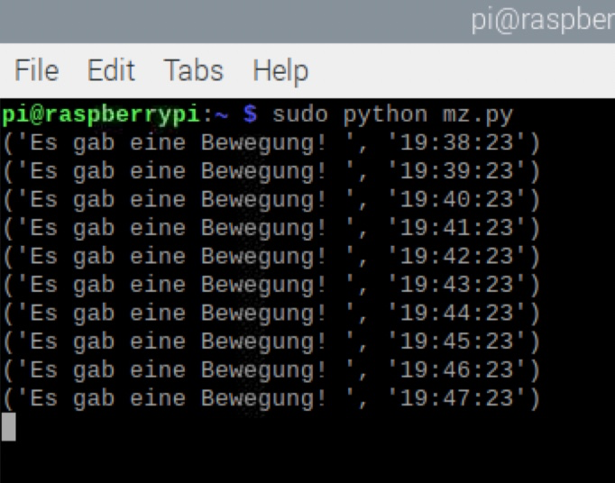
                                I also noticed, even if I added the ferrite beat, that the sensor recevied every minute excact on the second a signal

                                c06e06b8-0380-4a64-a040-2ef29f7c68ee-image.png

                                1 Reply Last reply Reply Quote 0
                                • FoziF Offline
                                  Fozi Project Sponsor @thgmirror
                                  last edited by

                                  @thgmirror said in PIR Sensor: false positive detections:

                                  It is not a step-down/up … it is called Pull-Up, resp Pull-Down.

                                  Are you dealing with 3D printing? Just asking, because step-down converters are quite popular for modding cooling fans in that hobby :beaming_face_with_smiling_eyes:

                                  HowTo: Replace PIR Sensor with a RCWL-0516 Microwave Sensor

                                  thgmirrorT 1 Reply Last reply Reply Quote 0
                                  • thgmirrorT Offline
                                    thgmirror @Fozi
                                    last edited by

                                    @fozi no, currently no 3D-printing, but may be in the future:-)

                                    1 Reply Last reply Reply Quote 0
                                    • Z Offline
                                      Zoltan @MZ-BER
                                      last edited by

                                      @mz-ber
                                      Apologies for the late response
                                      1, 2 and 3 is capacitors yes
                                      4 & 5 is inductors or coils. The rule is a Capacitor conduct high frequency but block low frequency. The coil or inductor is doing the opposite, and conduct low frequency but block high frequency. The whole idea is to short circuit any spikes on the power line as well as the data line to ground. This is quite a big low pass filter and you can make it smaller with less components.
                                      Remove 1
                                      Leave 4 & 2
                                      Replace 5 with a wire

                                      6 is a resister yes. 10 Kilo Ohm 1/4 watt is perfect

                                      The coils you can strip out of an old circuit board. If it looks like a wire wind coil and it measure less than 3 ohm then its perfect
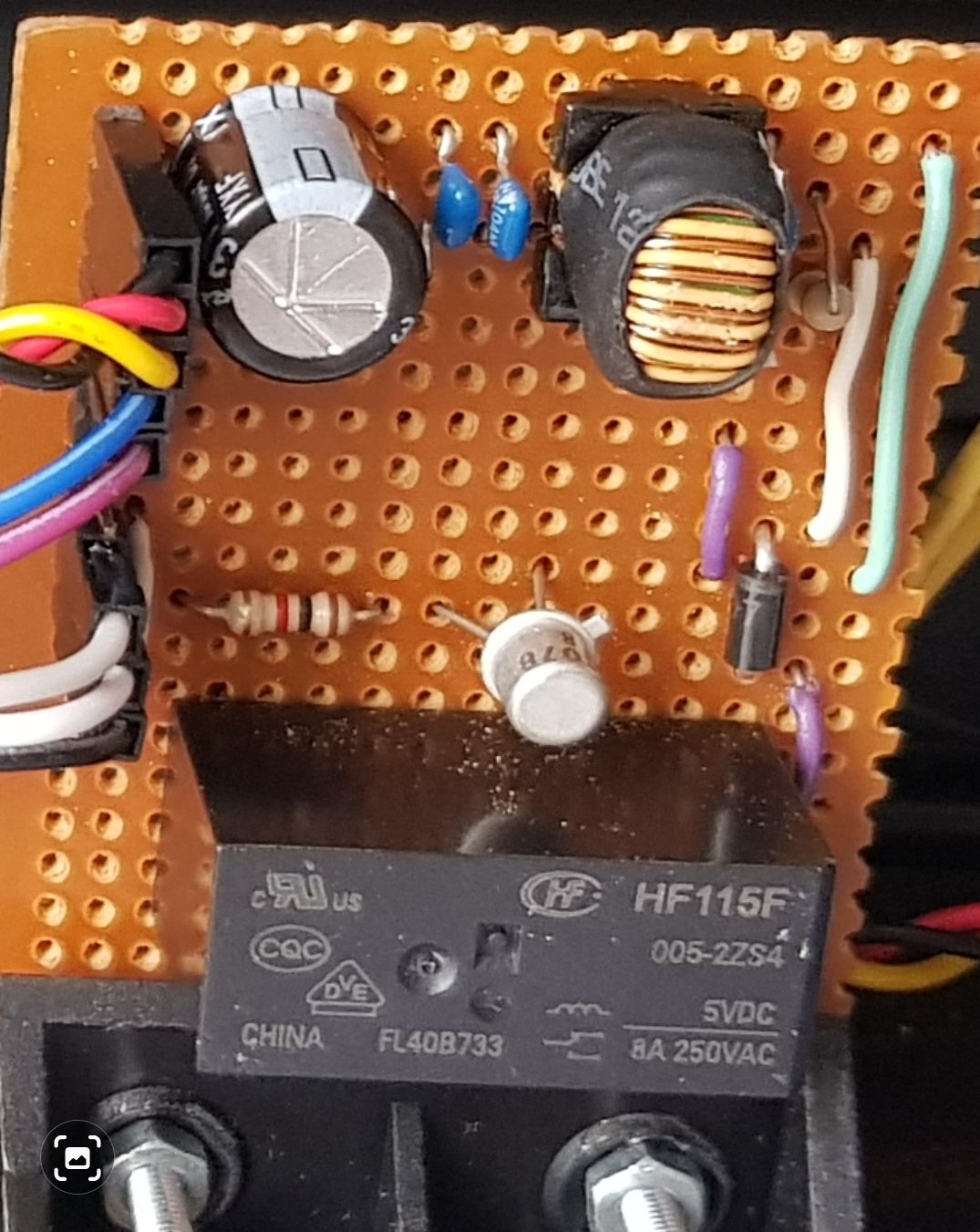
                                      1 Reply Last reply Reply Quote 0
                                      • Z Offline
                                        Zoltan @MZ-BER
                                        last edited by

                                        @mz-ber
                                        The controller board with the low pass filter
                                        Screenshot_20211203-180312_Gallery.jpg

                                        1 Reply Last reply Reply Quote 0

                                        Hello! It looks like you're interested in this conversation, but you don't have an account yet.

                                        Getting fed up of having to scroll through the same posts each visit? When you register for an account, you'll always come back to exactly where you were before, and choose to be notified of new replies (either via email, or push notification). You'll also be able to save bookmarks and upvote posts to show your appreciation to other community members.

                                        With your input, this post could be even better 💗

                                        Register Login
                                        • 1 / 1
                                        • First post
                                          Last post
                                        Enjoying MagicMirror? Please consider a donation!
                                        MagicMirror created by Michael Teeuw.
                                        Forum managed by Sam, technical setup by Karsten.
                                        This forum is using NodeBB as its core | Contributors
                                        Contact | Privacy Policy