MagicMirror Forum
    • Recent
    • Tags
    • Unsolved
    • Solved
    • MagicMirror² Repository
    • Documentation
    • 3rd-Party-Modules
    • Donate
    • Discord
    • Register
    • Login
    A New Chapter for MagicMirror: The Community Takes the Lead
    Read the statement by Michael Teeuw here.

    PIR Sensor: false positive detections

    Scheduled Pinned Locked Moved Hardware
    18 Posts 6 Posters 6.1k Views 6 Watching
    Loading More Posts
    • Oldest to Newest
    • Newest to Oldest
    • Most Votes
    Reply
    • Reply as topic
    Log in to reply
    This topic has been deleted. Only users with topic management privileges can see it.
    • thgmirrorT Offline
      thgmirror
      last edited by thgmirror

      Didn’t I said, I’m not an electrician?
      It is not a step-down/up … it is called Pull-Up, resp Pull-Down.
      Please see here for detailed (german) explanation: https://www.elektronik-kompendium.de/sites/raspberry-pi/2006051.htm

      MZ-BERM FoziF 2 Replies Last reply Reply Quote 1
      • MZ-BERM Offline
        MZ-BER @thgmirror
        last edited by

        @thgmirror Yep, that is what I’ll do next. Already ordered a starter kit with resistors, inductors and capacitors.

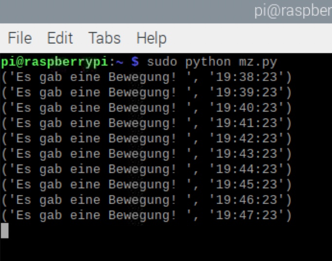
        I also noticed, even if I added the ferrite beat, that the sensor recevied every minute excact on the second a signal

        c06e06b8-0380-4a64-a040-2ef29f7c68ee-image.png

        1 Reply Last reply Reply Quote 0
        • FoziF Offline
          Fozi Project Sponsor @thgmirror
          last edited by

          @thgmirror said in PIR Sensor: false positive detections:

          It is not a step-down/up … it is called Pull-Up, resp Pull-Down.

          Are you dealing with 3D printing? Just asking, because step-down converters are quite popular for modding cooling fans in that hobby :beaming_face_with_smiling_eyes:

          HowTo: Replace PIR Sensor with a RCWL-0516 Microwave Sensor

          thgmirrorT 1 Reply Last reply Reply Quote 0
          • thgmirrorT Offline
            thgmirror @Fozi
            last edited by

            @fozi no, currently no 3D-printing, but may be in the future:-)

            1 Reply Last reply Reply Quote 0
            • Z Offline
              Zoltan @MZ-BER
              last edited by

              @mz-ber
              Apologies for the late response
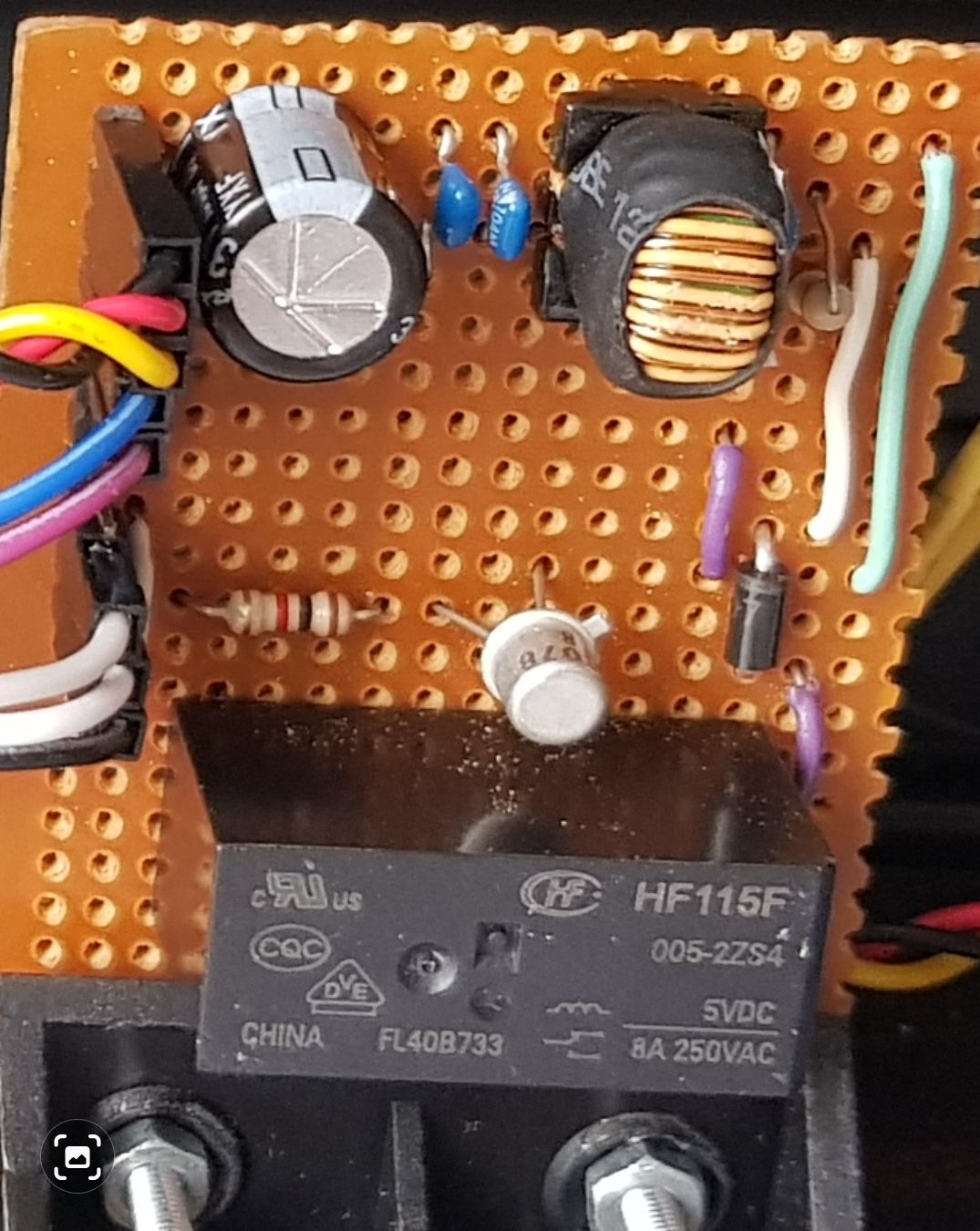
              1, 2 and 3 is capacitors yes
              4 & 5 is inductors or coils. The rule is a Capacitor conduct high frequency but block low frequency. The coil or inductor is doing the opposite, and conduct low frequency but block high frequency. The whole idea is to short circuit any spikes on the power line as well as the data line to ground. This is quite a big low pass filter and you can make it smaller with less components.
              Remove 1
              Leave 4 & 2
              Replace 5 with a wire

              6 is a resister yes. 10 Kilo Ohm 1/4 watt is perfect

              The coils you can strip out of an old circuit board. If it looks like a wire wind coil and it measure less than 3 ohm then its perfect

              1 Reply Last reply Reply Quote 0
              • Z Offline
                Zoltan @MZ-BER
                last edited by

                @mz-ber
                The controller board with the low pass filter
                Screenshot_20211203-180312_Gallery.jpg

                1 Reply Last reply Reply Quote 0
                • 1
                • 2
                • 1 / 2
                • First post
                  Last post
                Enjoying MagicMirror? Please consider a donation!
                MagicMirror created by Michael Teeuw.
                Forum managed by Sam, technical setup by Karsten.
                This forum is using NodeBB as its core | Contributors
                Contact | Privacy Policy