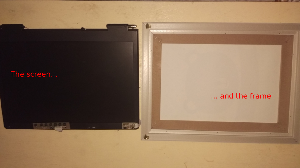
At the moment I only have the modules by default and some simple ones from third parties. In the future I hope to add some more, such as a presence detector to turn on the monitor when it detects movement. I’d like to show you some pictures of the project.
If you prefer, you can watch a video on youtube about my mirror in this link:
https://www.youtube.com/watch?v=JmT4wroDmCY (WITHOUT THE PIR AND THE RELAY)
https://www.youtube.com/watch?v=a5RfCQVqrJo&t=6s (WITH THE PIR, RELAY AND SCRIPT WORKING)

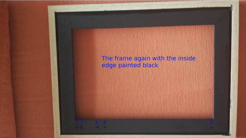
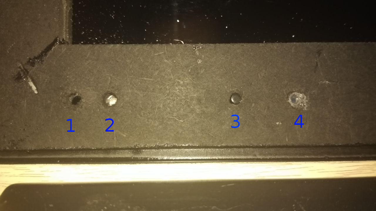
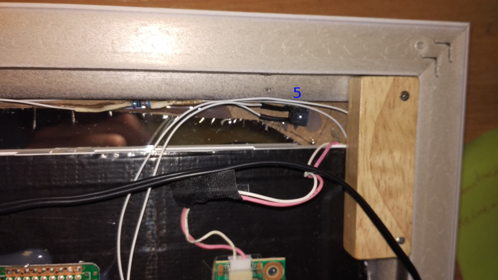
These little holes are for, from left to right:
1 - infrared receiver for the remote control of the controller board.
2 - led status of the screen, also included with the controller (on: green / off: red).
3 - pushbutton to turn on / off the screen (for now also the rpi zero is turned off, since it is connected to a usb of the controller, in the future I hope that the screen can be turned off independently).
4 - Activity LED of the raspberry (you have to follow these simple steps: https://sudomod.com/forum/viewtopic.php?t=1113).
5- RESET button (if the raspberry is hanging, it is a hard reset).
HARDWARE:

The Power Supply I’m using is a 12 V DC 2 A and works great for the controller board + raspberry Pi Zero W.
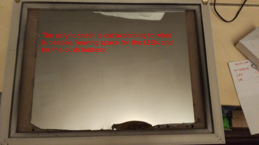
DETAILED VIEW
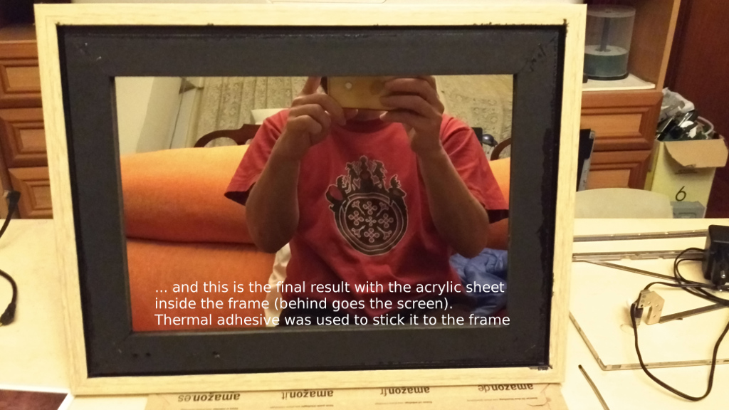
FINAL RESULT

NEW UPDATE (2018-07-09): INSTALATION OF THE PIR AND RELAY TO SWITCH ON/OFF SCREEN AUTOMAGICALLY
Well, I’ve finished my mirror installing the motion detector (PIR) and the relay. I’ve installed too one 18650 battery in case there is a blackout.
The basic idea of the motion detector is that when nobody are near the mirror, it turns off the scree, but the raspberry is still running. When somebody aproax the mirror, it turns on the screen. The PIR output goes into an input GPIO of the raspberry (22, BCM), then, on pin 25 (BCM) goes the input to the relay (output from the raspberry GPIO). And finally, the screen detector as an input to the GPIO (pin 6 BCM). It’s a simple circuit from the USB port of the controller board of the screen that is on level HIGH (3v) when screen is on, and level LOW (0v) when is off.
Here you can take a look at the script written in python for this purpose:
#!/usr/bin/python3

# PACKAGES NEEDED TO WORK:  sudo apt install python3 python3-rpi.gpio

# My screen has an USB port, that turns on when screen is on, and off when screen is off.
# So, I made a voltage divider with a few resistors to get 3 volts, to activate pin 6 (BCM)
# on the raspberry Pi. In this way, the script can 'know' if Screen is ON or OFF.

import RPi.GPIO as GPIO
import time
import subprocess
from subprocess import call

GPIO.setmode(GPIO.BCM)
GPIO.setup(22, GPIO.IN)		                  # PIR's output
GPIO.setup(6, GPIO.IN)                            # Screen power detector
GPIO.setup(25, GPIO.OUT)	                  # Relay Input
GPIO.setwarnings(False)

while (GPIO.input(6) == 0):                       # IF SCREEN IS ON
    if (GPIO.input(22) == 1):                     # PIR DETECTS MOTION
        call(('/opt/vc/bin/vcgencmd', ' display_power', '1'))
        GPIO.output(25, GPIO.HIGH)                # RELAY ACTIVATION
        time.sleep(3)
        GPIO.output(25, GPIO.LOW)
        time.sleep(60)                            # THE TIME WE WANT THE SCREEN TO STAY ON
        if (GPIO.input(22) == 1):                 # IF PIR DETECTS A NEW MOVEMENT,
            time.sleep(60)                        # ACTIVATES THE MIRROR ANOTHER AMOUNT OF SECONDS
        else:
            GPIO.output(25, GPIO.HIGH)           # WITH THIS LINE, THE SCREEN POWERS OFF TO SAVE ENERGY
            time.sleep(3)
            GPIO.output(25, GPIO.LOW)
    else:
        GPIO.output(25, GPIO.LOW)

while (GPIO.input(6) == 1):                       # IF SCREEN IS OFF
    if (GPIO.input(22) == 1):                     # PIR DETECTS MOTION
        call(('/opt/vc/bin/vcgencmd', ' display_power', '1'))
        GPIO.output(25, GPIO.LOW)               # SAME AS ABOVE, BUT THIS TIME DON'T ACTIVATE THE RELAY
        time.sleep(60)
        if (GPIO.input(22) == 1):
            time.sleep(60)
        else:
            GPIO.output(25, GPIO.HIGH)      # WITH THIS LINE, THE SCREEN POWERS OFF TO SAVE ENERGY, AGAIN
            time.sleep(3)
            GPIO.output(25, GPIO.LOW)
    else:
        GPIO.output(25, GPIO.LOW)

call(('/usr/bin/python3', '/home/pi/SCRIPTS/pir.py'))
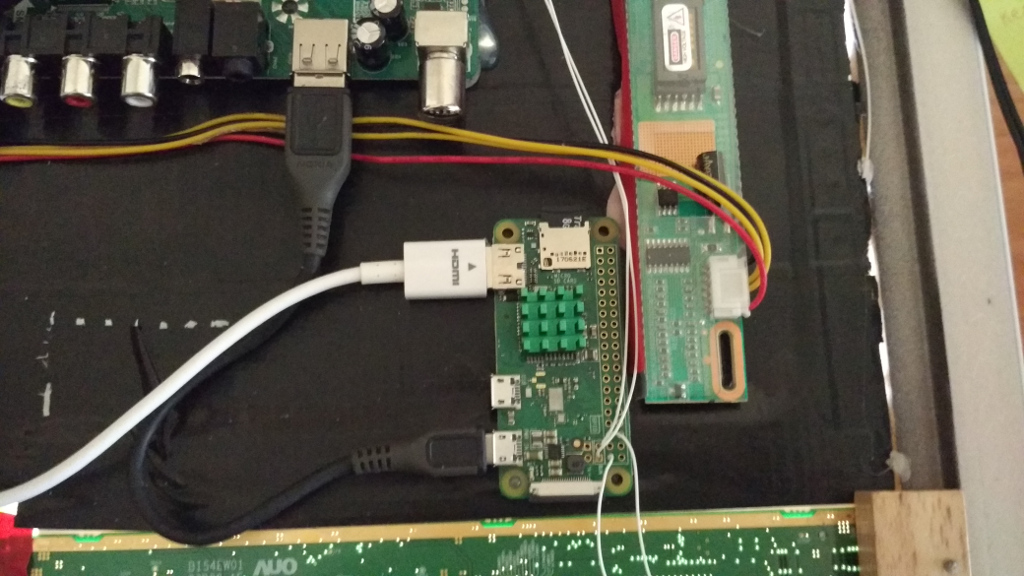
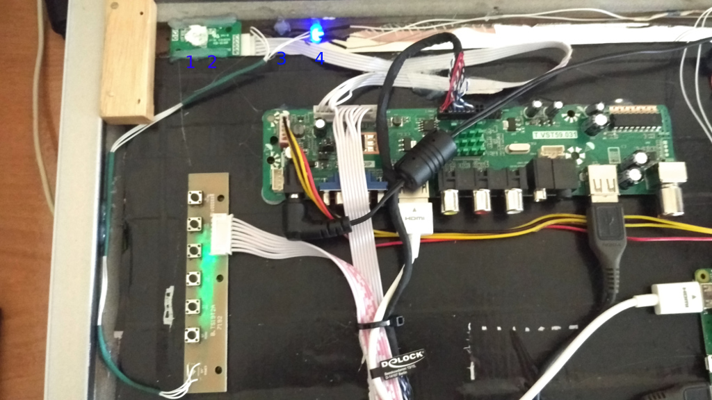
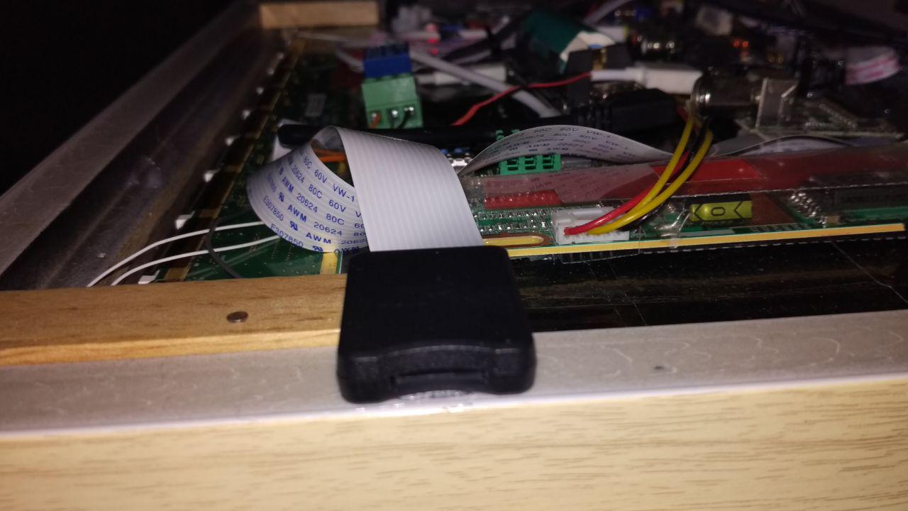
Here are some pictures of the back face of the mirror:
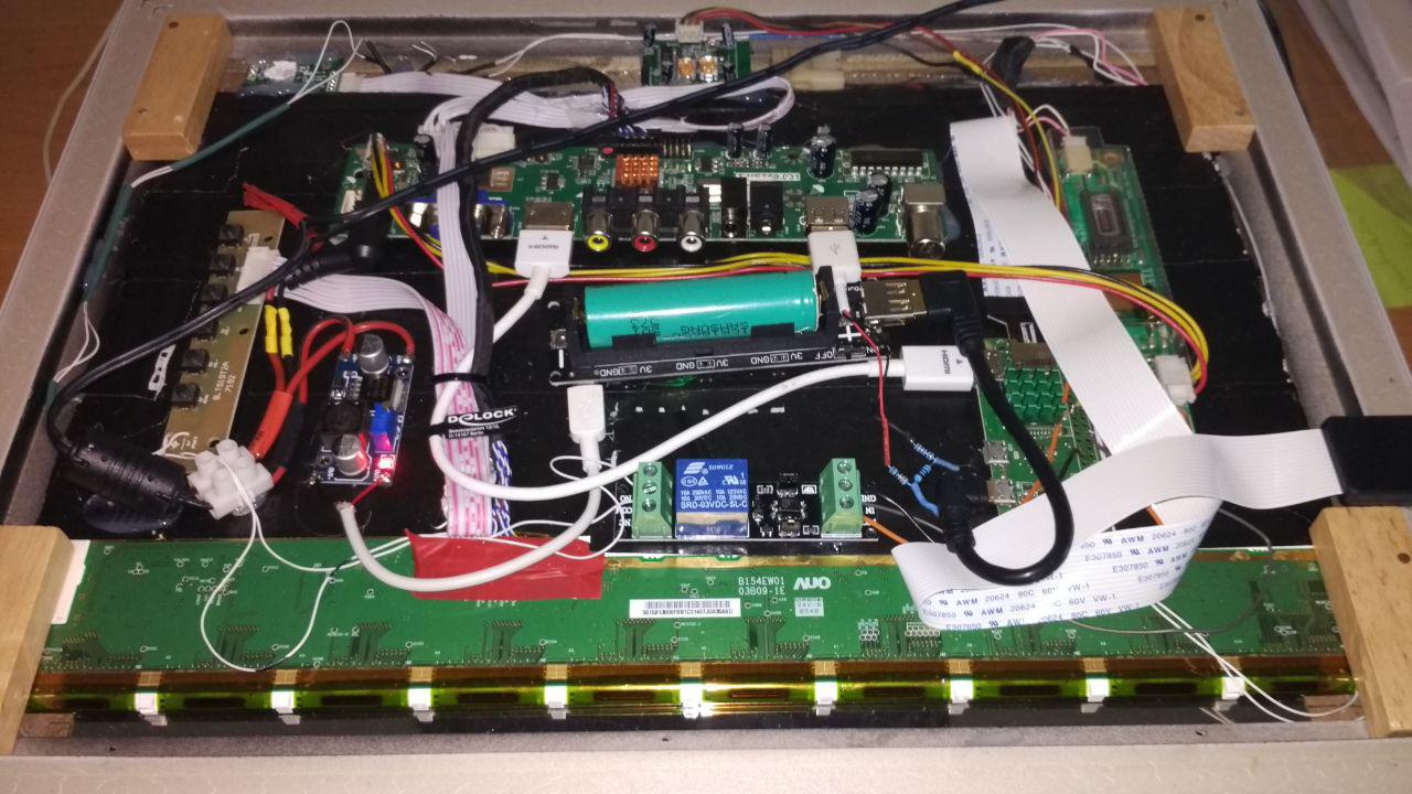
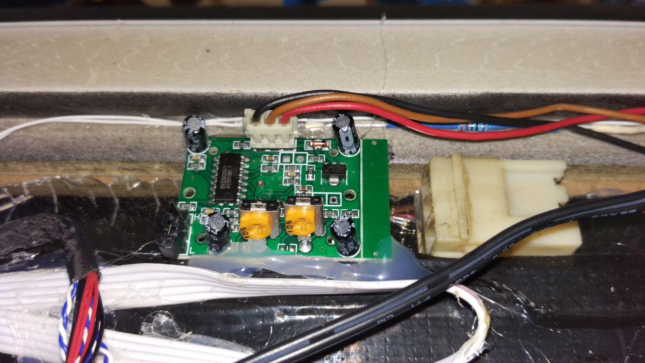
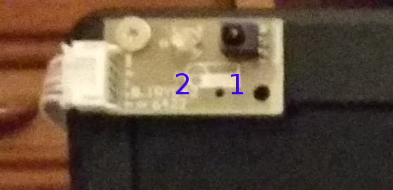
Detail of the PIR on the back face of the mirror…
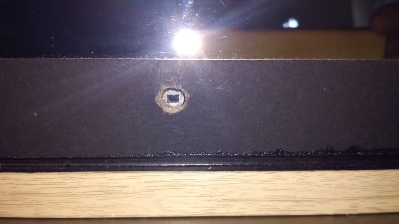
… and on the front face. I’ve made an 8 mm hole for the PIR detector (I think is a phototransistor, but I’m not sure)
Detail of the micro SD Extender to easily extract te micro sd card.
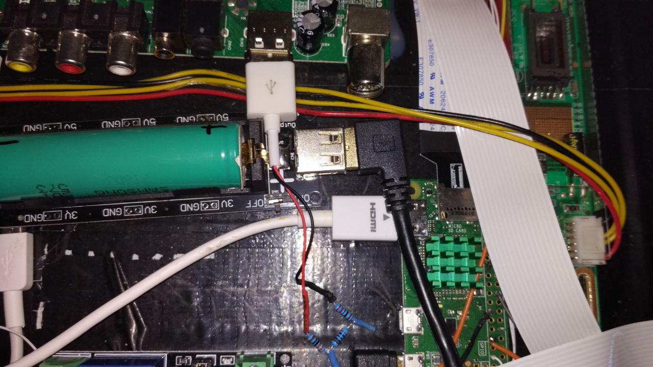
I’ve made a voltage divider with a few resistors to get 3 volts from the USB port of the screen. When the screen is on, the USB is on too, and vice versa. The 3 volts output of this voltage divider goes to pin 6 (BCM) of the raspberry.
MATERIAL’S LIST
OPTIONAL:
MATERIALS FOR THE MOTION DETECTOR