Read the statement by Michael Teeuw here.
UPDATE: Replaced my PIR-Sensor with a Doppler Microwave Sensor.
-
@lavolp3 Ah…now I got you.
There are two options to reduce the sensor range:
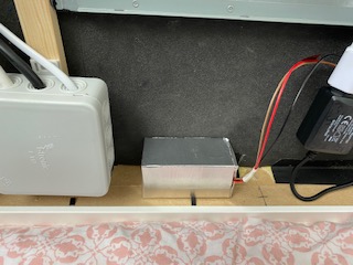
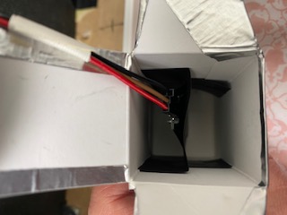
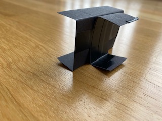
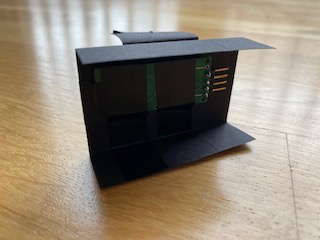
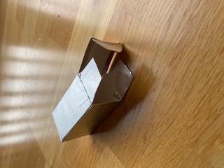
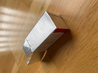
Option 1: The aluminum taped “Magic Box” like described here.
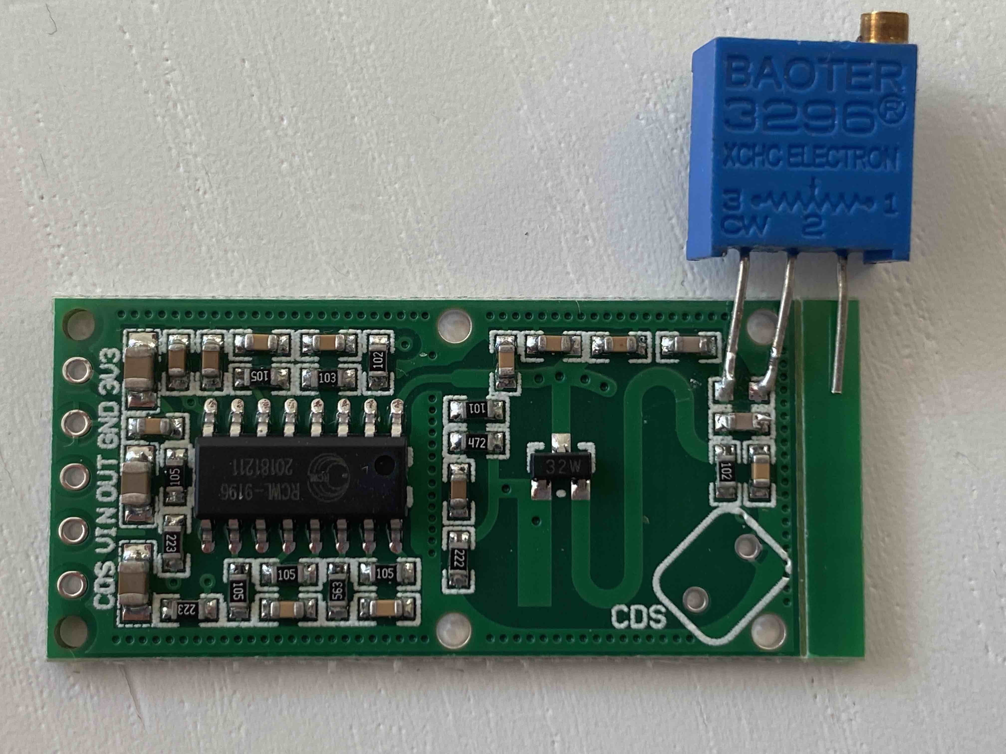
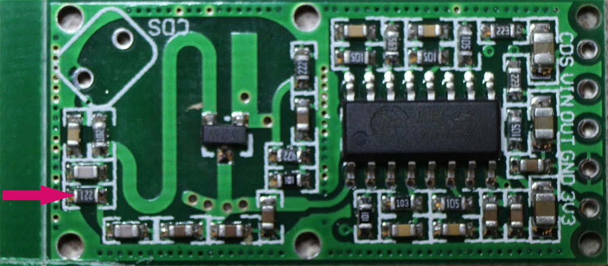
Option 2: Replacing a resistor on the sensor to reduce the sensor range.I haven’t yet tried option2, as I’m waiting for some parts to do it. As soon as I got them I’ll test that option and will give feedback. For the time beeing, I just can make a statement for option 1, which requires no additional resistor.
Maybe there is also an option 3, a combination of option 1 and 2…we’ll see.
-
@Mykle1 said in Replaced my PIR-Sensor with a Doppler Microwave Sensor.:
Excellent description. I like your innovation. I’m guessing this is going to replace the PIR sensor. I think most people have the same feeling as you about the appearance of the PIR. It does distract from the “magic”. Well done! :thumbsup:
That would be the idea…easier to ‘hide’… the PIR is nice but ugly.
-
@Fozi said in Replaced my PIR-Sensor with a Doppler Microwave Sensor.:
RCWL-0516 microwave sensor
Thank you so much for this…ordering one so I can get rid of the ugly PIR in my bathroom!!!
Awesome job!! -
@cowboysdude Thanks! I’m looking forward to your experiences with the sensor!
-
@Fozi
I’ll try this out hopefully tonight but not with an Aluminium tape but with aluminum foil. Should work as well as far as I can see. -
@lavolp3 yes, should do equally. I had some leftover of the tape and it was more convenient to apply. I found some post from you a few months ago, when you struggled to make the sensor work. I hope you get some better results now.
-
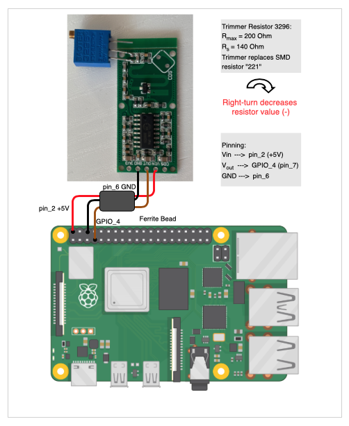
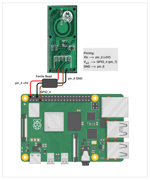
@Fozi Is there a wiring diagram for this? I know where the wires on my pi are and there two wires running to the sensor but where are they connected on the actual sensor?
Thanks!
-
@cowboysdude
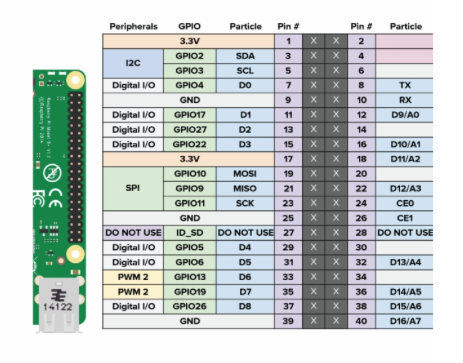
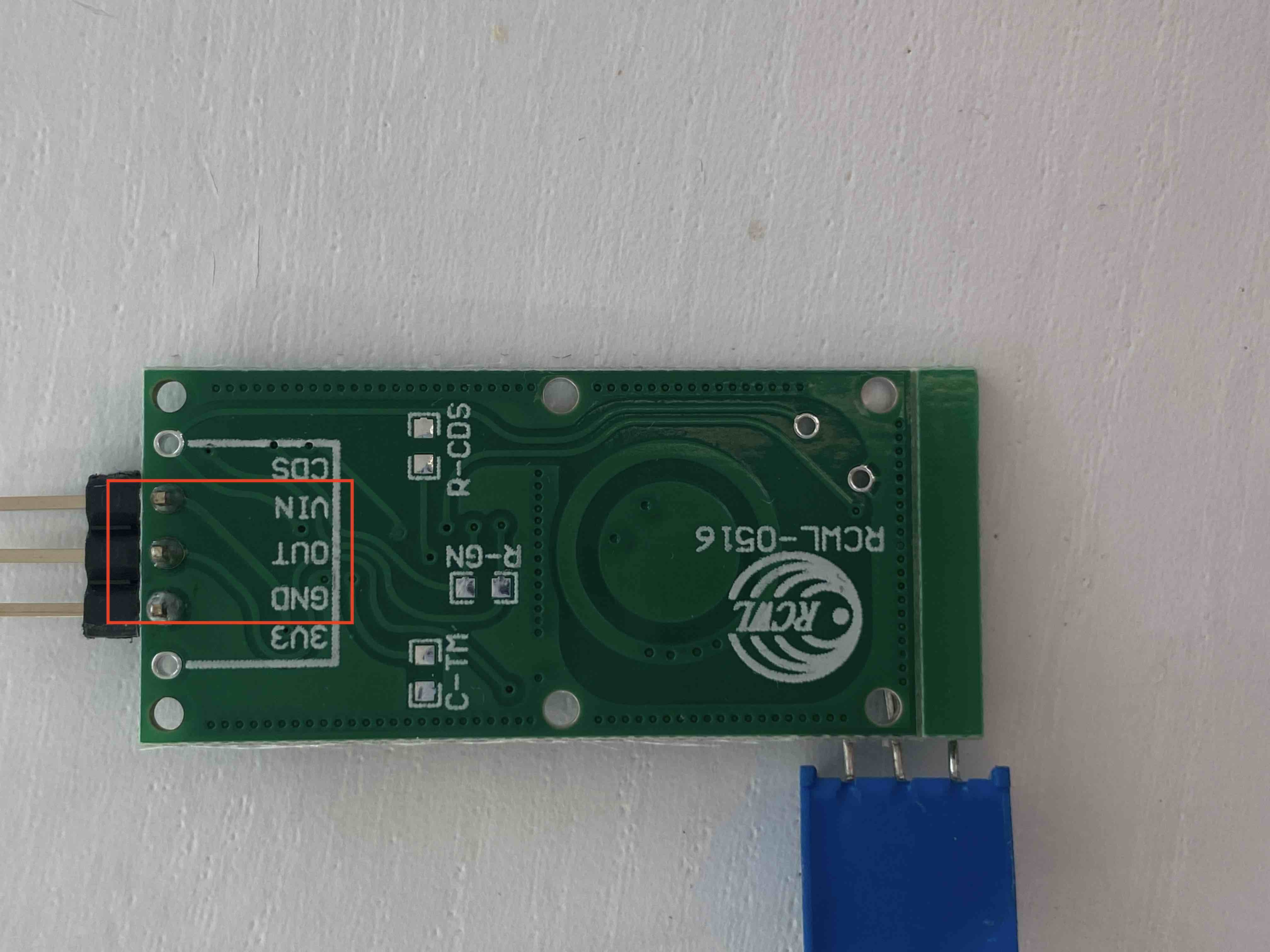
You only use Vin (5V), Vout and GND. CDS (for applying a photo diode) and 3V3 (delivers 3.3V output) remain unused. For Vout you can use also oher GPIO pins (labeled “Digital I/O” in the 2nd diagram), in case GPIO_4 is already used.The ferrite bead is optional. It is a left over from the PIR sensor I had attached. If you may need one, you can dismantle an old VGA cable and use that one.
Here the wireing diagram: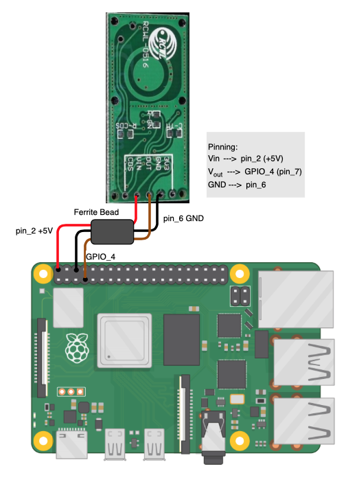
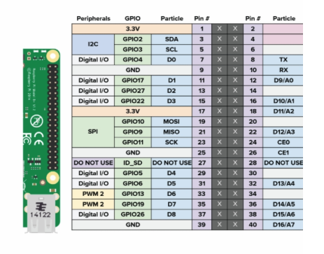
-
Super Awesome yet again!! Thank you! I don’t use the PIR module… I have a Python script I run behind everything. It works very well for me but this will work so nice, and now I can move it behind the glass!
Now if I can just remember where I put my ferrite beads… I know I have some … but where LOL
-
Hi folks,
sooner than expected I modified the sensor with a trimmer resistor.
For that I also updated my initial post and enhanced the tutorial, where now both options are described. Enjoy and give me your feedback, how that works for you.
