[image: 1641180643382-bf63b126-5665-4eb8-a071-213c2b82b82c-image.png]
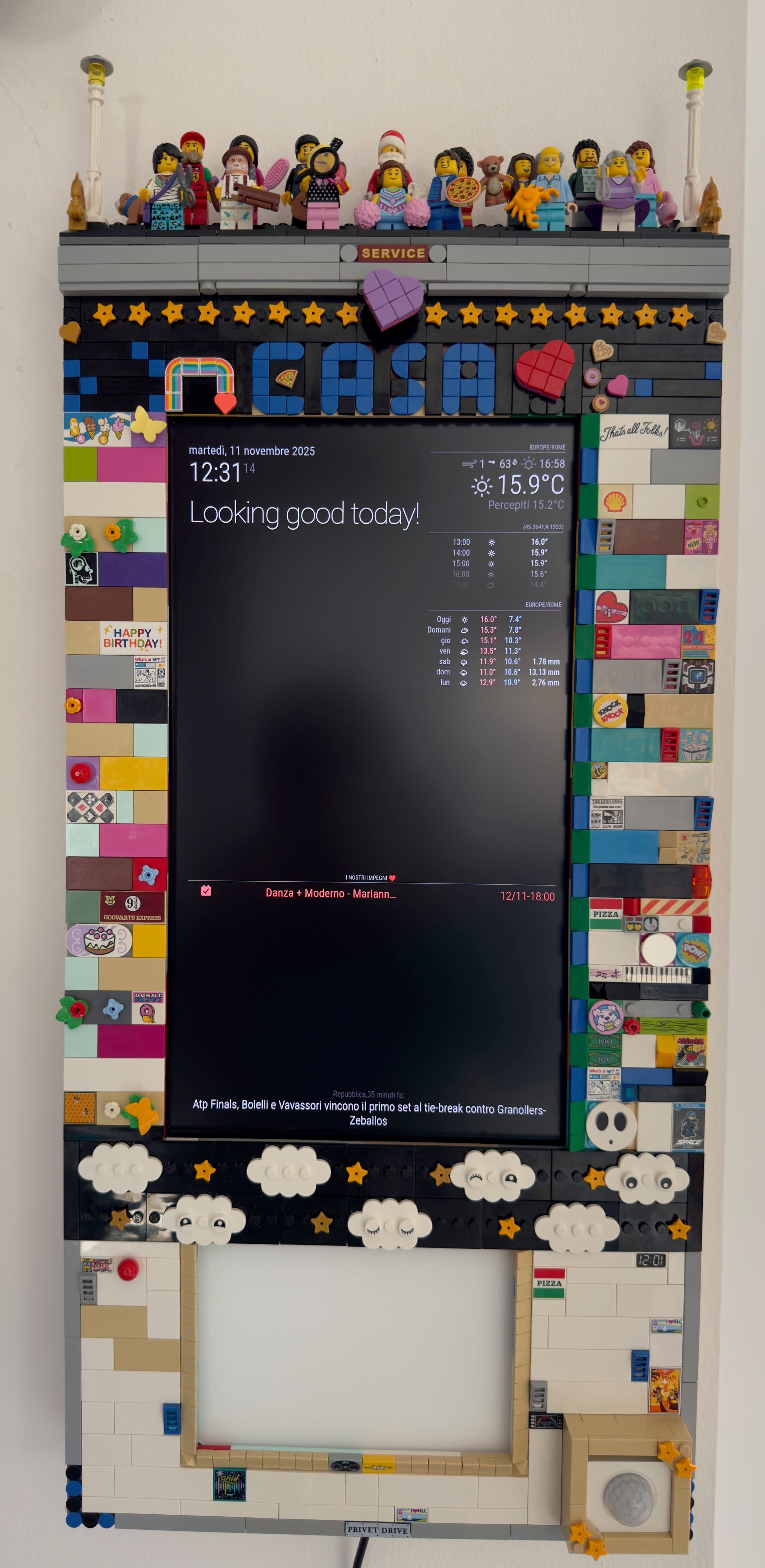
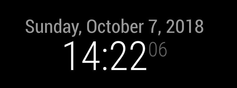
At the top of my Magic Mirror is a motion sensor that the Pi uses to turn on the TV when someone is in the room. This had the unfortunate side-effect of greeting me with a manufacturers sideways logo every morning, which was a bit annoying. This is a write-up on how I changed a TV’s splash screen from the this logo (picture #1) to something a little more personal (picture #2).
Disclaimer: these exact steps may not work on your MM and may very well brick your display, I would strongly suggest not attempting this unless: you’re happy to fork out for a new display, and you know what you’re doing
This write-up draws heavily on a post by Keegan Ryan titled “Spectre on a Television”. (https://web.archive.org/web/20190927050547/https://www.nccgroup.trust/us/about-us/newsroom-and-events/blog/2018/december/spectre-on-a-television/).
Tools:
Hot Air Rework Station + Soldering Iron
Screwdriver
Solder Paste + Wire
SOP8 to DIP8 Socket Adapter
BusPirate + USB Mini B
Logic Analyser
Wires
Linux PC / Laptop
A new splash screen! I used GIMP to make the retro text on mine :)
Step 1: Hardware Reverse “Engineering”
Before poking around the back of the TV, I unplugged it from the wall socket. I took great care to stay well clear of the power circuitry at all times, as mains power circuits can be dangerous even when unplugged.
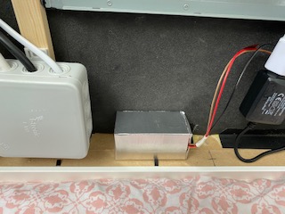
After taking the back of the TV off it was pretty easy to identify the power/control sections (below). I believe these are generally well separated and the power circuitry is usually directly connected to the TV power cable but results may vary.
[image: 1641180824315-0f70194a-e4e8-460d-8d72-aa6977990cf6-image.png]
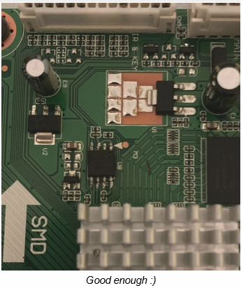
Looking a little closer at the controller board, I found an 8-pin chip that is a common form factor for SPI flash memory chips.
[image: 1641180847852-983bb2bb-99a3-4af6-ad91-00b4c190d461-image.png]
The markings on the back of the chip (winbond W25Q80BV - determined with great difficulty) confirm that it is a 3.3V Winbond Serial Peripheral Interface chip. Perfect for holding juicy data like splash screen images. From the datasheet the pinout is as follows:
[image: 1641180911416-c1956e4d-55b5-4763-813f-66a5039f0d00-image.png]
The pins I care most about are CLK (clock), DO (data out - MISO) and DI (data in - MOSI). Data in/out allows us to read/write to the chip, with the clock line dictating the transmission speed.
I confirmed that this is indeed an SPI chip with a logic analyser to read the first few seconds of the chip activity on TV boot (using sigrok/PulseView to capture and view).
[image: 1641181016733-d0d73a65-2f98-4ca3-8a56-06ce805ccca1-image.png]
So now “knowing” where the splash screen likely is, it was time to grab the chip off and try to replace it. Using a Hot Air rework station and some tweezers, I heated the solder connections sufficiently for them to melt, allowing me to pluck the SPI chip off the board.
Step 2: Dumping the Flash
Using a BusPirate and socket adapter, I dumped the flash from the SPI chip to my laptop for analysis. A couple of notes on this process:
Make sure to update the BusPirate to the latest firmware. Follow instructions at: http://dangerousprototypes.com/docs/Pirate-Loader_console_upgrade_application_(GNU/Linux,_Mac,_Windows) I didn’t have to update the bootloader, only the firmware
I was having a lot of difficulty trying to dump the flash using an Ubuntu Virtual Machine - I think this is a common issue. My workaround was to use a laptop that has Ubuntu installed.
[image: 1641181188697-8c323943-8ba8-42a9-93d3-ac456e7ee135-image.png]
Using the SOP8 to DIP8 socket adapter, I had full access to the Winbond chips pins. The wiring is as follows (note this may be different for the /WP and /HOLD pins depending on the particular SPI chip. Setting these logic level HIGH 3V3 allowed me to read/write):
[image: 1641181236374-4f1dad1b-923f-4cf4-ab45-2e3f8b75ee1d-image.png]
Plugging the BusPirate USB into the laptop I then dumped the flash using flashrom:
flashrom -V -p buspirate_spi:dev=/dev/ttyUSB0 -r flash.bin
Note: Replace “ttyUSB0” with your device name (check /dev/ folder or use dmesg when you plug the BusPirate in) and “flash.bin” with the output filename. -V enables verbose output, which offers some comfort that the command is working as it takes a while to run.
I now had a flash dump of the SPI chip :)
Note: I made sure to create backups of the original flash for if (when) things went pear-shaped.
Step 3: Analysing Flash and Replacing the Image
To start analysing the contents of the flash dump, I used binwalk which scans the file for “magic bytes” and reports what files it has found.
binwalk flash.bin
After running this command, binwalk should return all files that it can find within the dump (including their location or “offset” in this file). I was fortunate enough to find a few jpegs which was a good sign. Extracting now with:
binwalk --dd='.*' flash.bin
[image: 1641181387622-7a18559d-3bdb-431e-bef8-8f0a45d40000-image.png]
Gives us a folder of extracted files with some promising images!
[image: 1641181411417-fe2a4d71-f382-4a78-a836-54d21c95a9c5-image.png]
There are 4 files in the extracted folder - 3x jpegs images and 1x TIFF image data. 2 of the jpegs are thumbnails with the third being the actual full image. Binwalk helpfully outputs the location/offset of these files in the original command, so fingers crossed I can just write whatever I want over the top and it’ll be happy? Could it be that easy?
The aim is to replace the image starting at offset 0x2759C8 with the custom splash screen. This appears to be the actual full image file, with the others being thumbnails embedded within.
A few things to note when making your replacement TV splash screen (all of this can be done using GNU Image Manipulation Program):
Make sure the image size matches what you are replacing (my original image was 1366 x 768 px).
Confirm the orientation is correct! My Magic Mirror is portrait orientated, and so I had to rotate my replacement image 90 degrees to the right to match it.
Make sure the replacement image size is less than the original image in the flash, otherwise you’ll be writing over other data which the TV likely will not be amenable to.
Note: binwalks extracted folder reported a size of 1.5MB for each of the extracted files, which is much larger than the actual image sizes in the flash. I do not know why binwalk was incorrect (and would appreciate any thoughts on this), but by manually searching for bytes “FF D9” (jpeg EOF) I determined that the replacement splashscreen should be about 200 kb.
After the brand new splash screen is made (I followed this tutorial to create the 80s style retro text) it’s time to start rewriting our flash. First I made a copy of the flash to write over:
cp flash.bin flash-edited.bin
Then, using standard Unix tools it was relatively easy to replace raw bytes of the flash binary at a specific offset. I essentially cut/pasted over the old image and crossed my fingers that the TV wouldn’t complain. Using dd:
dd conv=notrunc if=images/new_splash_2759C8.jpeg of=flash-edited.bin bs=1 seek=$((0x2759C8))
With “images/new_splash_2759C8.jpeg” being the new splash screen (if=input file), and “flash-edited.bin” being the file to write over. Using a block size of 1, the seek option skipped 0x2759C8 “blocks” and began writing. The $(()) operation converts this value to decimal = 2578888 for the dd command.
Then, I used flashrom to write flash-edited.bin to the SPI chip via the BusPirate:
flashrom -V -p buspirate_spi:dev=/dev/ttyUSB0 -w flash-edited.bin
Time to test it out! I soldered on some jumper wires and connected the chip back to the TV.
[image: 1641181959020-d31b2a3c-666e-4c7e-a625-7bab561db2df-image.png]
[image: 1641181995170-a35b65b2-3e06-4815-9fd3-719925191bac-image.png]
Step 4: Put my TV back together
To make the changes permanent, I used the Hot Air Station with some solder paste to resolder the chip back in its original position.
[image: 1641182031157-82690f23-7e31-4857-b5b5-e64235f45a75-image.png]
Conclusion:
This was a fun project that exposed me to a lot of interesting topics. I hope this information helps anyone else who is trying to add a personalised touch to their MM display.
Please comment with any feedback, suggestions or questions - cheers and thanks for reading
