Read the statement by Michael Teeuw here.
UPDATE: Replaced my PIR-Sensor with a Doppler Microwave Sensor.
-
Preface:
I’ve already described in detail how to reduce the sensor range of the RCWL-0516 sensor by building it into a cardboard box, which is wrapped in a aluminum foil (Option 1). But I found another more advanced solution (Option 2) by replacing a specific resistor on the sensor with an adjustable trimmer resistor. This option requires some soldering, but thats’s not as difficult as it might appear. I also enhanced this tutorial with your feedback to have everything in one place.Disclaimer: I’ll take of course no responsibility or liability, if anything breaks on your sensor, RPi or mirror. But I think this is a self-evident matter.
Like many of us, I have a PIR-Sensor installed on myMM to switch the display on and off and to save power while it is not in use.
For my MM i had an AM312 sensor mounted under the lower frame, bar pointing to the ground. That position was not ideal due to the limited viewing angle of 50 deg to the front. So I had to stand rather close to the mirror to switch the display on.
Further, such a PIR-sensors looks like an wart on the frame, especially when you have no real options to mount it unobstursively and it messes up the hole design.While looking for an alternative, I stumbled over the RCWL-0516 microwave sensor, which detects motion via the Doppler principle. This sensor has following characterisics:
(more details here)- it is rather small and thin and can be placed secretly everywhere inside the mirror
- very cheap (ca. 1-2€)
- easy to install with 3 pins
- works without any modifications with MMM-PIR-sensor module
- works through glass
- works omni-directional (360 deg)
- has a typical range of ca. 7m
But the last two bullets (omni-directional radiation and detection, long sensor range) are two issues you have to be aware of.
The RCWL-0516 works even through walls and can detect motions in adjacent rooms, which of course produces false positives and switches the display on when not desired.So how to limit the range?
There are posibilities to replace the SMD resistor with a trimmer poti (200 Ohms and less) between GND and antenna as described here, but this requires some soldering skills as the SMD resistor is quite tiny.
Option1: The “Magic Box”:
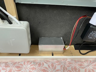
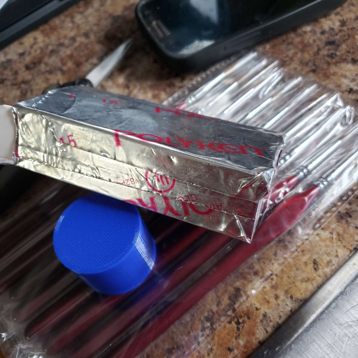
I went a different way by putting the sensor in a small card box and wrapping some adhesive aluminum tape around it to damp the radiation around the sensor, except the front where the sensor points to the glass.
I made some test and found out that putting the aluminum tape directly on the sensor (of cours with a thin isolation layer inbetween) reduces the sensitivity of the sensor to about 1-2 cm, which renders the sensor useless.
Thus I figured there must be an air gap between the sensor and the aluminum tape of ca. 1cm. So I made a simple frame of card board, which holds the sensor inside the center of the box to provide enough space. I put the sensor intentionally in the middle of the box instead of directly to the “front” side to reduce the radiation and detection angle a bit more.Here a some pictures of the housing:
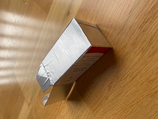
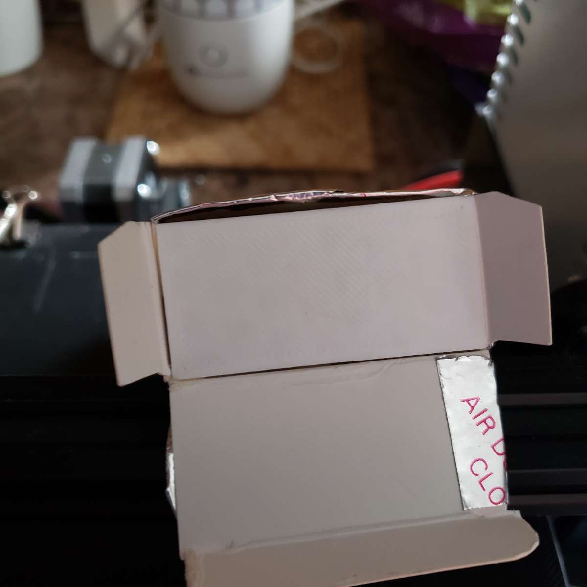
You see, the front-side of the box is NOT covered with aluminum tape. This side will be pointing to the mirror glas. All other five surfaces of the box are taped.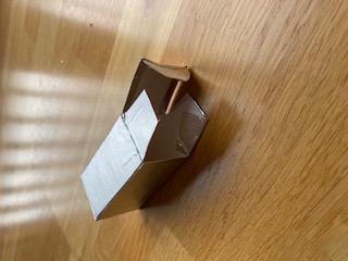
This is the backside.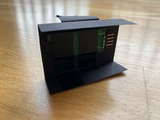
The simple frame construction which holds the sensor in the center of the box…like this…
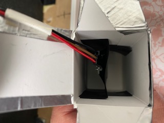
The box is then put inside the frame with the untaped side facing to the glass.Cross-section through the box: || | || || | || 1 cm gap || 1cm gap | || | taped sensor UN-taped backside front to the mirrorWireing of the sensor:
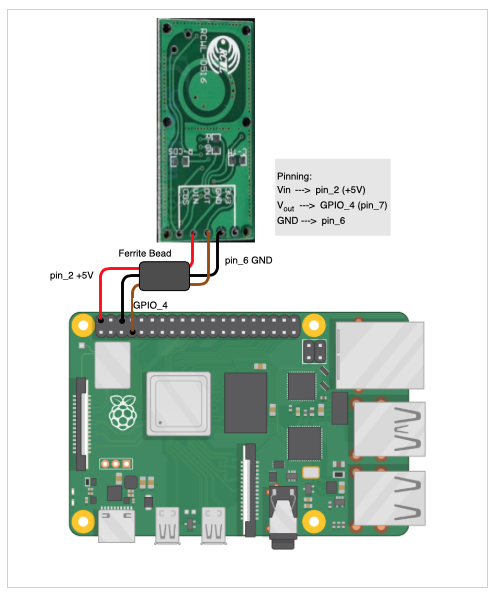
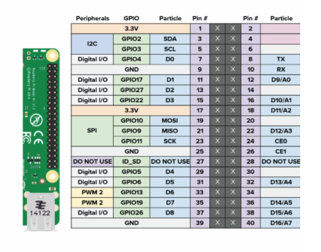
You only use Vin (5V), Vout and GND. CDS (for applying a photo diode) and 3V3 (delivers 3.3V output) remain unused. For Vout you can use also oher GPIO pins (labeled “Digital I/O” in the 2nd diagram), in case GPIO_4 is already used.
The ferrite bead is optional. It is a left over from the PIR sensor I had attached. If you may need one, you can dismantle an old VGA cable and use that one.
And thats it!The sensor is wired like any conventional PIR sensor to the the RPi with Vin = 5V, GND and a Vout=I/O-Pin of your choice.
As mentioned, before you can continue to use your favourite PIR module, like e.g. MMM-PIR-Sensor without any modifications.Option 2: Replacing the antenna to GND resistor:
On the sensor is a tiny SMD resistor soldered, wich is labeled with "221 (=220 Ohm).
To reduce the sensor range this resistor can be replaced with a smaller resistor value. The smaller the resistor, the shorter the range.
As the room layouts, characterisics of the walls (dry wall, concrete, stone, wood walls, tiles,….) differ from home to home and individual requirements, we’ll take an adjustable trimmer resistor to find the fitting value.What we need:
- Soldering iron and some soldering braid
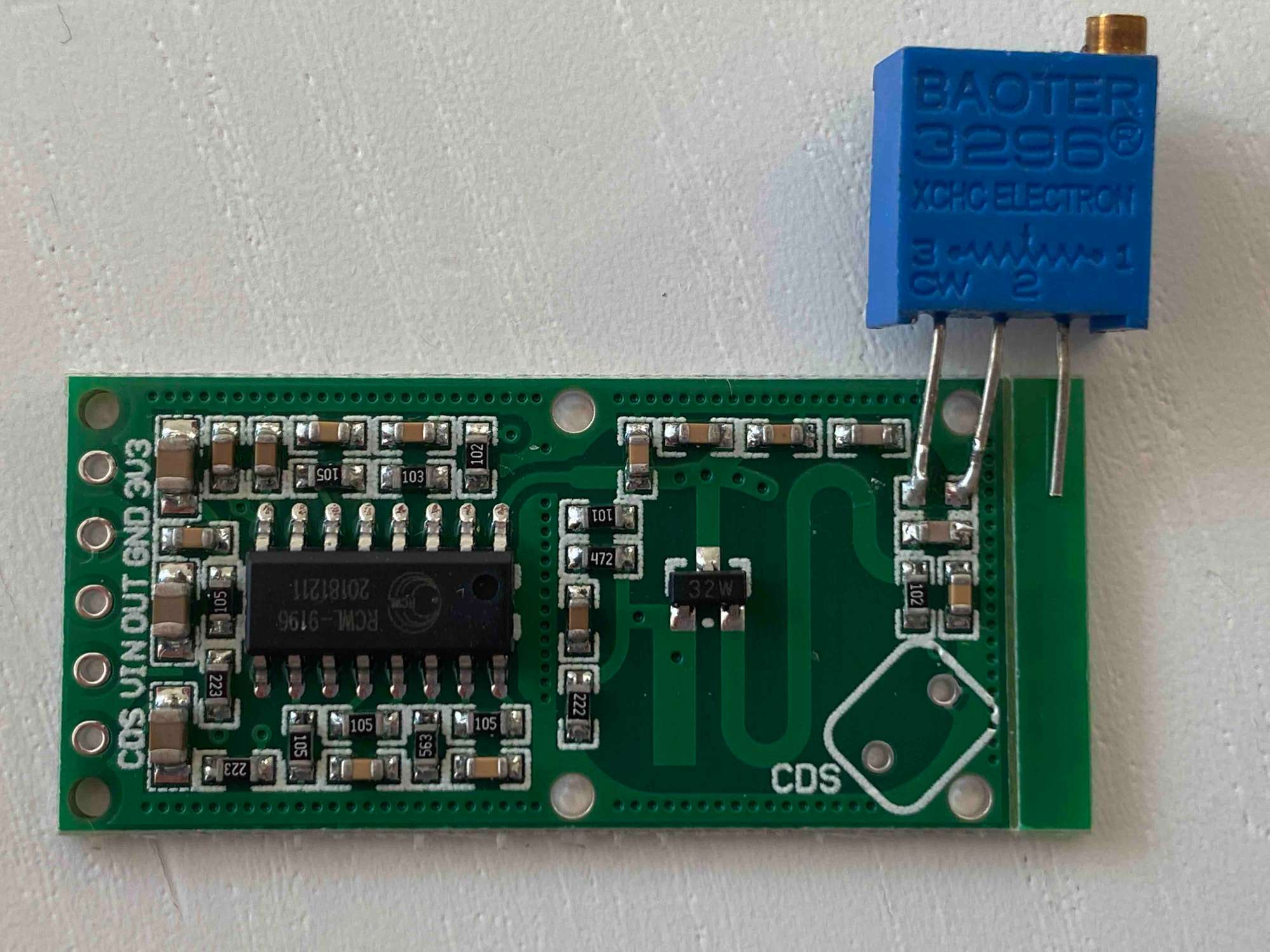
- Trimmer resistor, e.g. 3296 W201 with 200 Ohm (max. resitor value)
- Multi-meter, which can measure resistors
- Small screwdriver
- angled header pins
First we remove the “221” labeled resistor on the resistor (see red arrow)
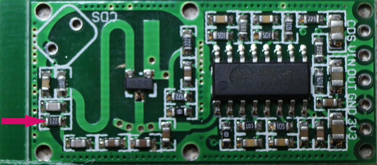
This requires some soldering skill, but with a little exercise it can be removed very easily. There are hundreds of great tutorials on youtube, which you can follow. I used this simple method:
https://www.youtube.com/watch?v=NjswgMtwXawBefore we solder the trimmer resistor, I’d recommend to adjust roughly the resistor value, as later it might be quite cumbersome. Take a multi-meter, which can measure electric resistors and adjust it to 150 Ohm. This value reduces to sensor range to ca. 1m. From there, you can then in creas or decreace the resistor until it fits you.
The next step is to solder the trimmer sesistor on the sensor like this. The third pin remains unused an can be clipped away later if desired.
Then solder the header pins on the left where you connect the sensor with the GPIO of the Rpi
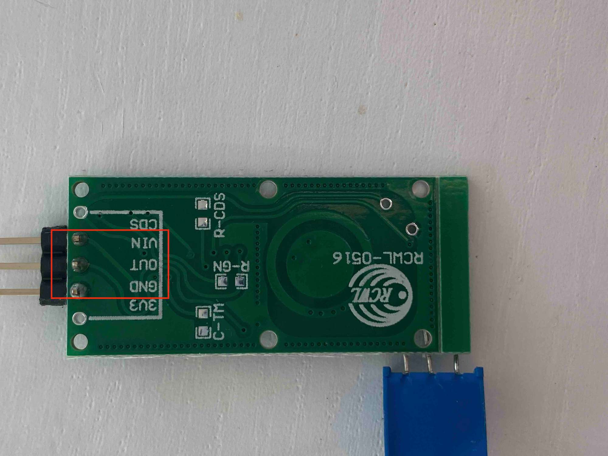
The CDS (for applying a photo diode) and 3V3 pin (delivers 3.3V output) remain unused.Then connect the sensor to the RPI
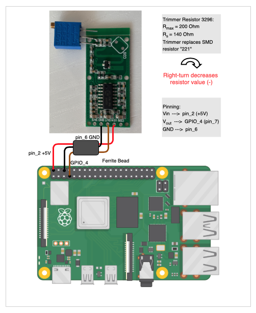
Again, you only use Vin (5V), Vout and GND. CDS (for applying a photo diode) and 3V3 (delivers 3.3V output) remain unused. For Vout you can use also oher GPIO pins (labeled “Digital I/O” diagram above), in case GPIO_4 is already used.
The ferrite bead is optional. It is a left over from the PIR sensor I had attached. If you may need one, you can dismantle an old VGA cable and use that one.
In the last step you mount the sensor in the frame, start MM and adjust the resistor with a small screw driver a few turns to more or less range. Probably you’ll need a second person, which moves outside the room to test if the range is good enough while you adjust the trimmer.
Conclusion?
Option 1:
The sensor inside that box works just as desired for me. I made “exhaustive tests” with my daughters jumping around in the adjacent rooms and floors and had no false positives. This of course applies to the layout of our house and your milage may vary. But I think that this simple approach could be useful for others, too.Option 2:
This a more advanced and sophisicated approach, which works in my setup also as desired. Of course it depends very much on how your rooms are layed out and what characteristic your walls have. And you need a bit excercise in soldering. On the other hand you need no extra space inside the frame for the “Magic Box”.Now it’s up to you which option you want to go. Start with Option 1 and see how your results are, and if you wish then go on with Option2.
-
@Fozi very cool work, and results!
-
@sdetweil Thanks! It’s fun to contribute to the community and this project.
If anyone has a better solution for the housing, I’d be happy if you post it here, too.
I am very sure that there a more creative approaches than mine. -
Excellent description. I like your innovation. I’m guessing this is going to replace the PIR sensor. I think most people have the same feeling as you about the appearance of the PIR. It does distract from the “magic”. Well done! :thumbsup:
-
@Mykle1 thank you so much!
-
@Fozi thanks for the great explanation. I tried to get one working but it didn’t work maybe for the exact reason you described.
Do you have it directly behind the glass now in your box? Without an additional resistor?
What do you think is the recognition length? -
@lavolp3 I have placed the sensor inside the box along the center axis, so that there is a gap of ca. 1cm to the front and the back of the box.
the UN-taped frontside is directly touching the glass. The top, bottom as well as the left and right side are taped, too. Only the front is not taped.
In the scetch below you can see how I adjusted the sensor inside the box as seen from the side.
Two reasons why I set the sensor in the middle of the box:- Direct contact with the tape prohibited fully the detection.
- The taped top, bottom and lateral sides reduce the detection angle like a funnel compared to having the sensor mounted directly to the untaped front.
An additional resistor is not necessary, as it goes in high state when motion is detected (just like a PIR).
Hard to say what the detection range really is after that mod. My bathroom is really small but I would guess that if should be 2m or mor to the front.
Cross-section through the box: || | || || | || 1 cm gap || 1cm gap | || | taped sensor UN-taped backside front to the mirror -
@Fozi said in Replaced my PIR-Sensor with a Doppler Microwave Sensor.:
An additional resistor is not necessary, as it goes in high state when motion is detected
I thought a resistor could reduce the range by limiting the signals coming from the sensor. But I’m a complete failure when it comes to electronics so what do I know…
-
@lavolp3 Ah…now I got you.
There are two options to reduce the sensor range:
Option 1: The aluminum taped “Magic Box” like described here.
Option 2: Replacing a resistor on the sensor to reduce the sensor range.I haven’t yet tried option2, as I’m waiting for some parts to do it. As soon as I got them I’ll test that option and will give feedback. For the time beeing, I just can make a statement for option 1, which requires no additional resistor.
Maybe there is also an option 3, a combination of option 1 and 2…we’ll see.
-
@Mykle1 said in Replaced my PIR-Sensor with a Doppler Microwave Sensor.:
Excellent description. I like your innovation. I’m guessing this is going to replace the PIR sensor. I think most people have the same feeling as you about the appearance of the PIR. It does distract from the “magic”. Well done! :thumbsup:
That would be the idea…easier to ‘hide’… the PIR is nice but ugly.
-
@Fozi said in Replaced my PIR-Sensor with a Doppler Microwave Sensor.:
RCWL-0516 microwave sensor
Thank you so much for this…ordering one so I can get rid of the ugly PIR in my bathroom!!!
Awesome job!! -
@cowboysdude Thanks! I’m looking forward to your experiences with the sensor!
-
@Fozi
I’ll try this out hopefully tonight but not with an Aluminium tape but with aluminum foil. Should work as well as far as I can see. -
@lavolp3 yes, should do equally. I had some leftover of the tape and it was more convenient to apply. I found some post from you a few months ago, when you struggled to make the sensor work. I hope you get some better results now.
-
@Fozi Is there a wiring diagram for this? I know where the wires on my pi are and there two wires running to the sensor but where are they connected on the actual sensor?
Thanks!
-
@cowboysdude
You only use Vin (5V), Vout and GND. CDS (for applying a photo diode) and 3V3 (delivers 3.3V output) remain unused. For Vout you can use also oher GPIO pins (labeled “Digital I/O” in the 2nd diagram), in case GPIO_4 is already used.The ferrite bead is optional. It is a left over from the PIR sensor I had attached. If you may need one, you can dismantle an old VGA cable and use that one.
Here the wireing diagram: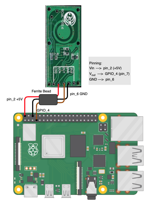

-
Super Awesome yet again!! Thank you! I don’t use the PIR module… I have a Python script I run behind everything. It works very well for me but this will work so nice, and now I can move it behind the glass!
Now if I can just remember where I put my ferrite beads… I know I have some … but where LOL
-
Hi folks,
sooner than expected I modified the sensor with a trimmer resistor.
For that I also updated my initial post and enhanced the tutorial, where now both options are described. Enjoy and give me your feedback, how that works for you. -
@Fozi nice update… very clear and helpful
-
Once again excellent work! I love the trimmer it’s a great idea for those with limited space!
For some strange reason I have left a gap at the top of my mirror that fits what I build perfectly!
I wanted a bigger mirror so I bought the glass oversized and centered the monitor in it :)This, accidently, left me enough room to fit this in perfectly!
So what I did was design a “T” with a whole in it to mount the sensor and install it inside the box.
I am a contractor so having aluminum tape was not a hard thing for me to come up with.Thank you @Fozi for this entire project! Allows me to get rid of the ugly PIR sensor outside the mirror and place a sensor behind the scenes but works as intended.
So for me option 1 works great! This won’t work for everyone but in my case perfect!
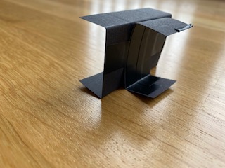
[Have NOT installed it in the mirror yet but will today]Here’s the pictures.
Box
3d PLA Printed ‘T’
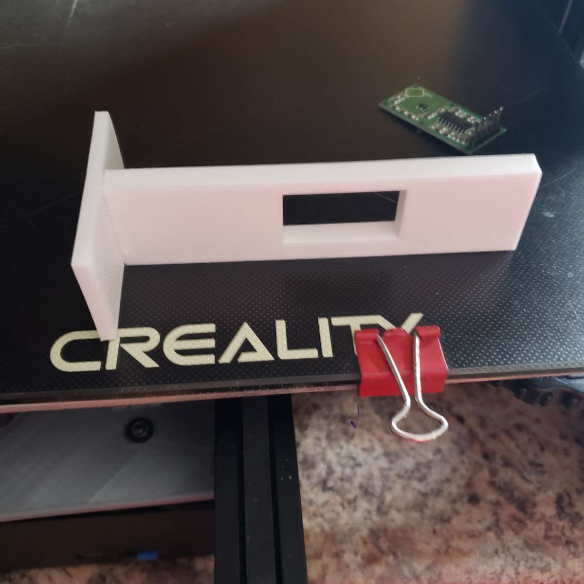
Fits inside of box
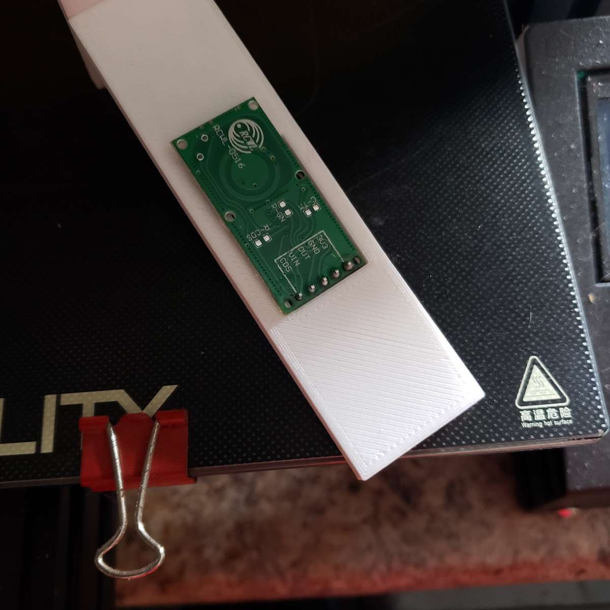
Picture of sensor on ‘T’
Once again, Thank you @Fozi !!!
Hello! It looks like you're interested in this conversation, but you don't have an account yet.
Getting fed up of having to scroll through the same posts each visit? When you register for an account, you'll always come back to exactly where you were before, and choose to be notified of new replies (either via email, or push notification). You'll also be able to save bookmarks and upvote posts to show your appreciation to other community members.
With your input, this post could be even better 💗
Register Login